Zynq UltraScale MPSoC Base TRD 2017.1 - Design Module 7
Zynq UltraScale MPSoC Base TRD 2017.1 - Design Module 7
Table of Contents
Design Overview
This module shows how to add a 2D convolution filter between the capture pipeline and the display. The 2D filter is implemented purely in software using the OpenCV library.
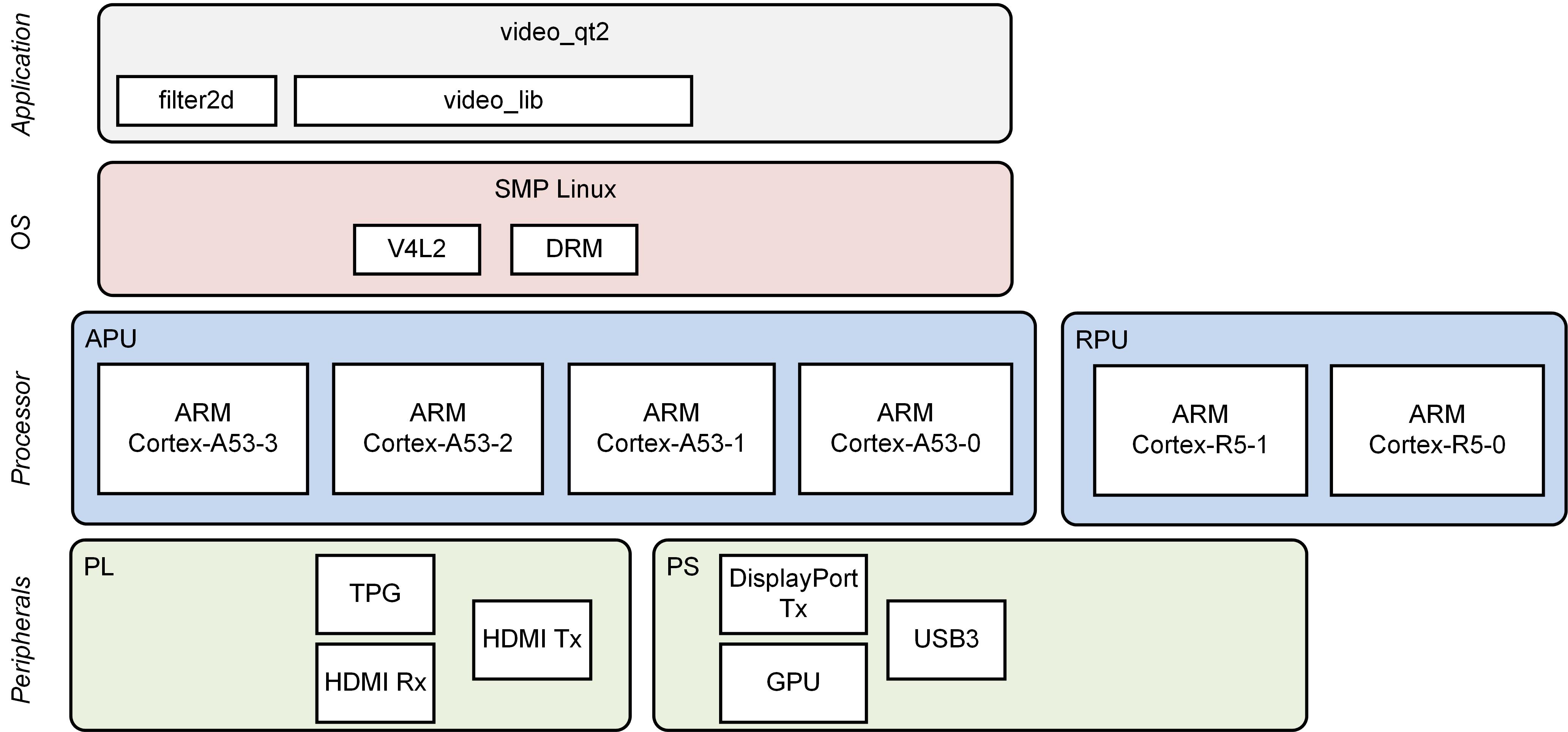
Design Components
This module requires the following components:
- zcu102_base_trd (SDSoC)
- filter2d (SW)
- video_lib
- video_qt2
Build Flow Tutorials
2D Filter Sample
This tutorial shows how to build the OpenCV version of the 2D filter sample based on the Base TRD SDSoC platform.
- Follow the steps in design module 5 to create a new workspace and to import the video_lib and video_qt2 projects. Otherwise, open the existing SDx workspace.
% cd $TRD_HOME/apu/video_app
% sdx -workspace . &&
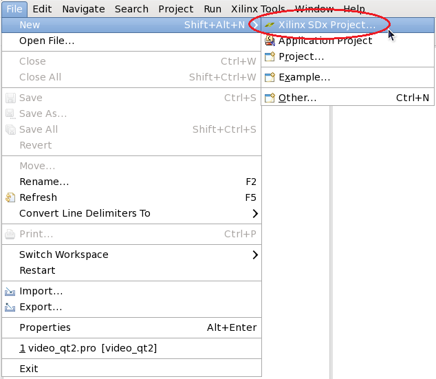
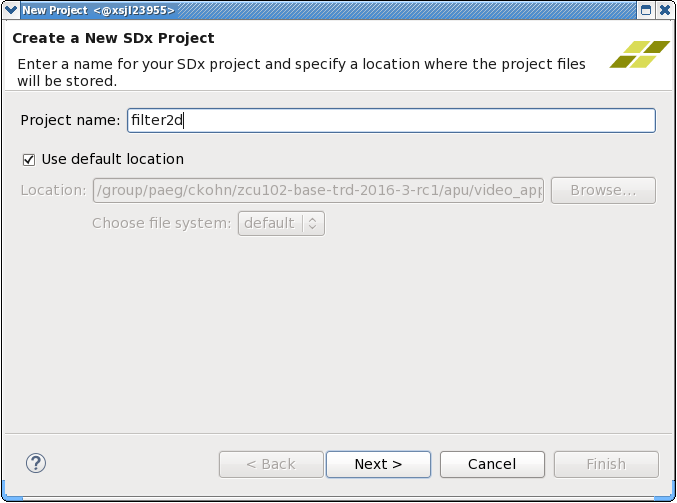
- Create a new SDx Project
- Enter 'filter2d' as project name
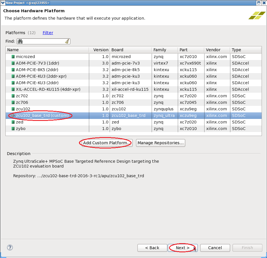
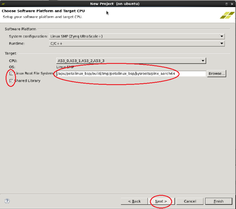
- Click 'Add Custom Platform', browse to the $TRD_HOME/apu/sdsoc_pfm directory and confirm. Select the newly added zcu102_base_trd (custom) platform for production silicon or zcu102_es2_base_trd (custom) for ES2 silicon from the list and click 'Next'.
- Check the 'Shared Library' box and click 'Next'.
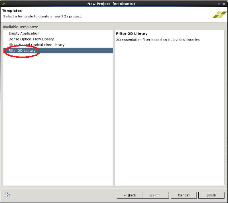
- Select the '2D Filter Library' template and click 'Finish'.
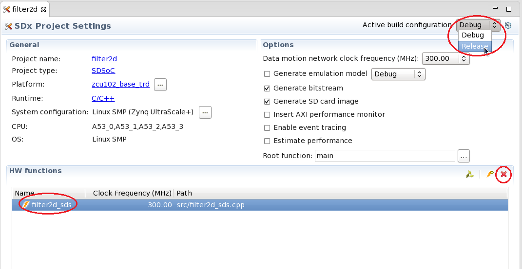
- Change the 'Active build configuration' to Release in the SDx Project Settings window.
- Remove the filter2d_sds HW function by highlighting the function name and clicking the red X symbol.
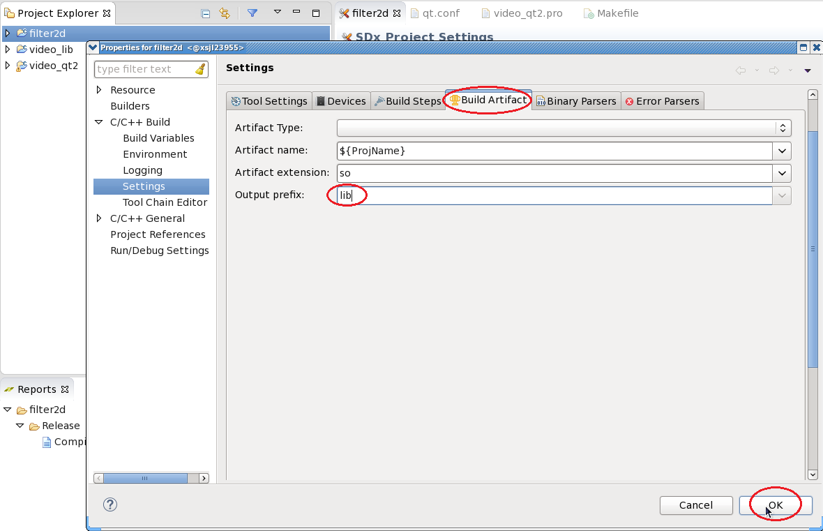
- Right-click the filter2d project, select 'C/C++ Build Settings'. Navigate to the 'Build Artifacts' tab and add the output prefix 'lib'. Click OK.
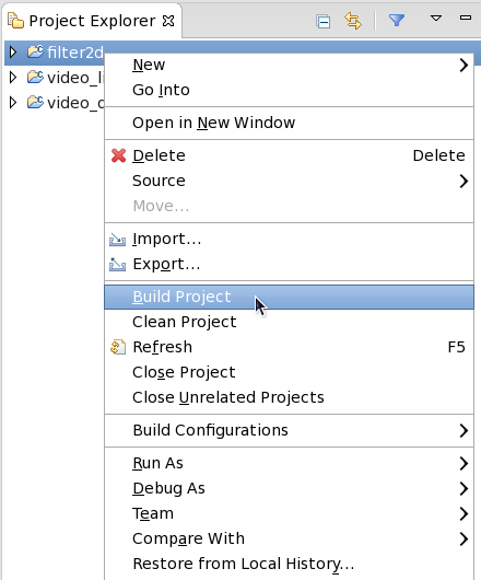
- Right-click the filter2d project and select 'Build Project'.
- Copy the content of the generated sd_card folder to the dm7 SD card directory
% mkdir -p $TRD_HOME/images/dm7
% cp -r filter2d/Release/sd_card/* $TRD_HOME/images/dm7/
Video Qt Application
This tutorial shows how to build the video library and the video Qt application.
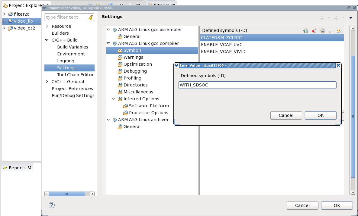
- Right-click the video_lib project, select 'C/C++ Build Settings'. Add the symbol 'WITH_SDSOC' and click OK.
- Source the Qt setup script and generate the Qt Makefile.
% cd $TRD_HOME/apu/video_app/video_qt2
% source qmake_set_env.sh
% qmake video_qt2-dm7.pro -r -spec linux-oe-g++
- Close SDx and reopen the same workspace so the Qt environment gets picked up correctly by eclipse. If you have sourced the qmake_set_env.sh script in the same shell before opening SDx, you can skip this step.
- Right-click the video_qt2 project and click 'Build Project'.

- Copy the generated video_qt2 executable to the dm7 SD card directory.
% cp video_qt2 $TRD_HOME/images/dm7/
Run Flow Tutorial
- See here for board setup instructions.
- Copy all the files from the $TRD_HOME/images/dm7 SD card directory to a FAT formatted SD card.
- Power on the board to boot the images; make sure INIT_B, done and all power rail LEDs are lit green.
- After ~30 seconds, the display will turn on and the application will start automatically, targeting the max supported resolution of the monitor (one of 3840x2160 or 1920x1080 or 1280x720). The application will detect whether DP Tx or HDMI Tx is connected and output on the corresponding display device.
- The SD card file system is mounted as read-only at /media/card. The remount the file system as read-write, run
% remount
- To re-start the TRD application with the max supported resolution, run
% run_video.sh
- To re-start the TRD application with a specific supported resolution use the -r switch e.g. for 1920x1080, run
% run_video.sh -r 1920x1080
- The user can now control the application from the GUI's control bar (bottom) displayed on the monitor.
- The user can select from the following video source options:
- TPG (SW): virtual video device that emulates a USB webcam purely in software
- USB: USB Webcam using the universal video class (UVC) driver
- TPG (PL): Test Pattern Generator implemented in the PL
- HDMI: HDMI input implemented in the PL
- A 2D convolution filter can be turned on and different filter presets can be selected; the following filter modes are available:
- OFF - accelerator is disabled/bypassed
- SW - accelerator is run on A53 using OpenCV implementation
- HW - accelerator is run on A53 using HLS implementation.
Note: Since the HLS code is running on the A53 in this module instead of hardware, it actually performs slower than the OpenCV "SW" mode. In the next module, the HLS code is accelerated on the PL hardware which will result in a significant speedup.
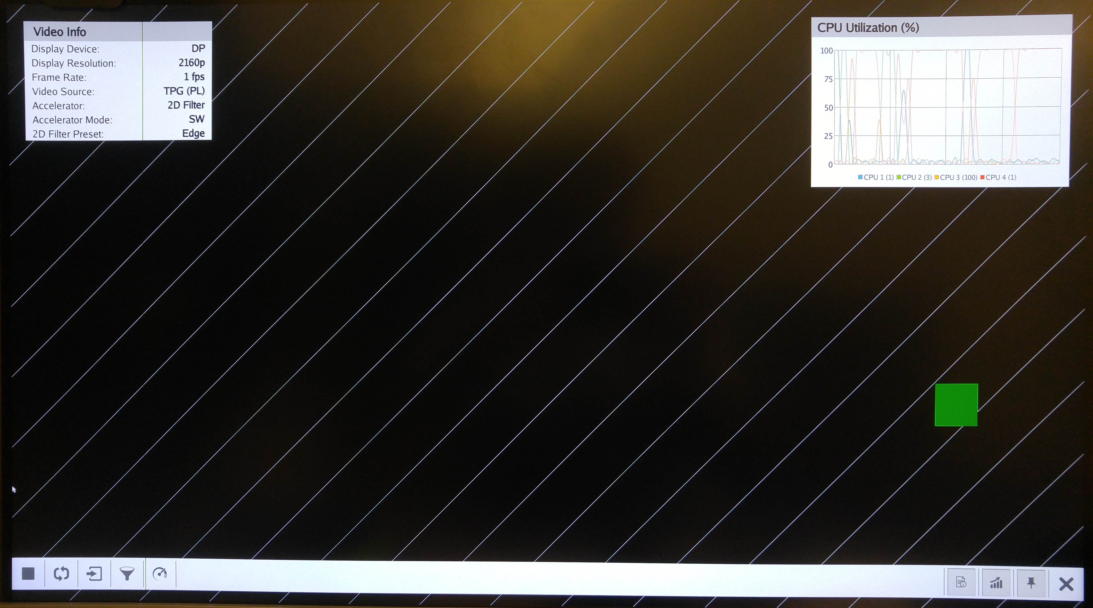
- The video info panel (top left) shows essential settings/statistics.
- The CPU utilization graph (top right) shows CPU load for each of the four A53 cores.
Return to the Design Tutorials Overview.
© Copyright 2019 - 2022 Xilinx Inc. Privacy Policy