Zynq UltraScale+ MPSoC VCU TRD 2018.2 - Design Module 1
Zynq UltraScale+ MPSoC VCU TRD 2018.2 - Design Module 1
Table of Contents
The below sections describe the build and run flow tutorials of the DM1 - PL HDMI Video Capture design. For the overview, software tools and system requirements, and design files, follow the link below:
1.1 Board Setup
- Connect the Micro USB cable into the ZCU106 Board Micro USB port J83, and the other end into an open USB port on the host PC. This cable is used for UART over USB communication.
- Insert the SD card with the images copied into the SD card slot J100.
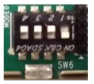
- Set the SW6 switches as shown in the below Figure. This configures the boot settings to boot from SD.
- Connect 12V Power to the ZCU106 6-Pin Molex connector.
- Connect one end of HDMI cable to board’s P7 stacked HDMI connector (lower port) and another end to HDMI source.
- For USB storage device, connect USB pen drive (Optional).
- For SATA storage device, connect SATA data cable to SATA 3.0 port. (Optional).
- Set up a terminal session between a PC COM port and the serial port on the evaluation board (See the Determine which COM to use to access the USB serial port on the ZCU106 board for more details).
- Switch ON SW1 to power the ZCU106 board.
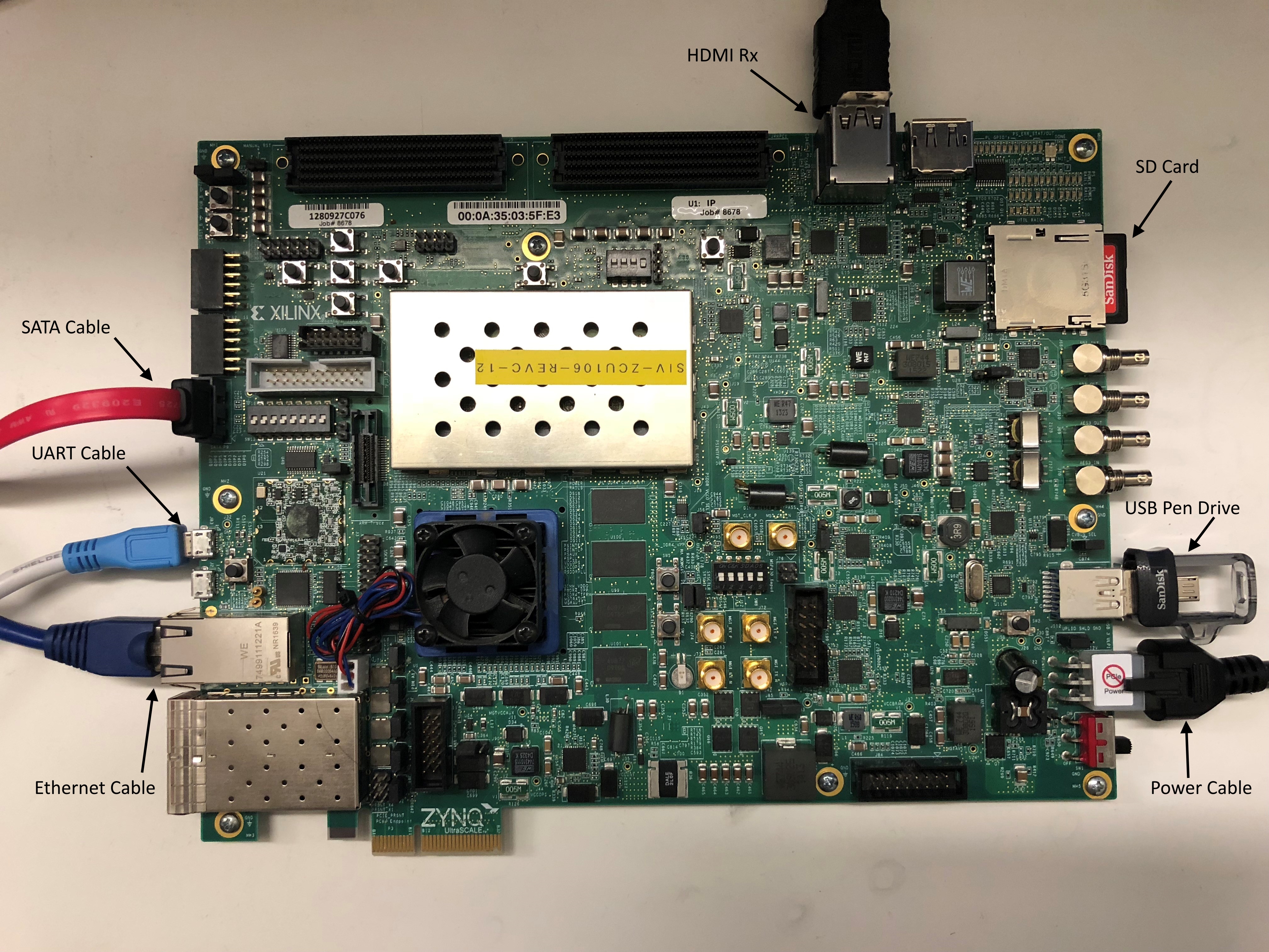
The figure below shows the ZCU106 board connections for HDMI RX design.
It takes about a minute for Linux to boot. The user may miss the boot sequence while the terminal session is being configured.
Determine which COM to use to access the USB serial port on the ZCU106 board.
Make sure that the ZCU106 board is powered on and a micro USB cable is connected between ZCU106 board and host PC. This ensures that the USB-to-serial bridge is enumerated by the PC host.
Open your computer's Control Panel by clicking on Start > Control Panel.
Note that the Start button is typically located in the lower left corner of the screen. Occasionally, it is in the upper left corner.
- Click Device Manager to open the Device Manager window. Note: You may be asked to confirm opening the Device Manager. If so, click YES.
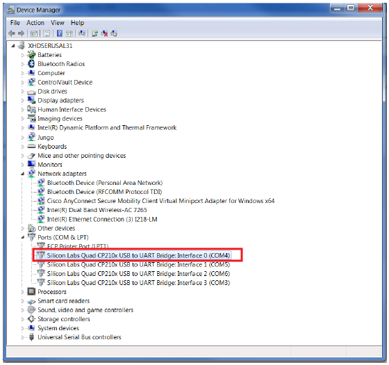
- Expand Ports (COM & LPT).
- Locate the Silicon Labs Quad CP210x USB to UART Bridge: Interface 0 (COM#).
- Note down the COM Port number for further steps.
- Close the Device Manager by clicking the red X in the upper right corner of the window.
Launch any Terminal application like Tera term to view the serial messages
- Launch Tera Term and open the COM port that is associated to Silicon Labs Quad CP210x USB to UART Bridge: Interface 0 of the USB-to-serial bridge.
- Set the COM port to 115200 Baud rate, 8, none, 1 –Set COM port.
- Power ON the board which has SD card. It boots Linux on board.
1.2 Run Flow
- Setup the board as explained in “Board Setup” Section.
- Prepare the SD card. Use SD formatter tool to format the SD card , https://www.sdcard.org/downloads/formatter_4/
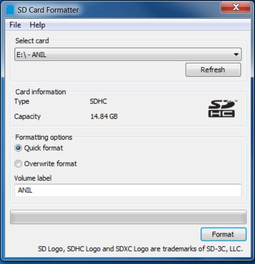
Please note that Windows formatter can't be used and partition should be FAT32, not FAT.
- Copy all the files from the $TRD_HOME/images/hdmirx_vcu/ SD card directory to a FAT32 formatted SD card.
- Power on the board; make sure INIT_B, done and all power rail LEDs are lit green.
- After ~30 seconds, the display will turn ON, and will get the command prompt on serial console.
NOTE: The SD card file system is mounted at /media/card. Optional storage medium SATA and USB are mounted at /media/sata and /media/usb respectively.
1.2.1 GStreamer Application (vcu_gst_app)
The vcu_gst_app is a command line multi-threaded Linux application that uses the vcu_gst_lib interface similar to vcu_qt. The command line application requires an input configuration file (input.cfg) to be provided in the plain text. Refer to the Appendix A - Input Configuration File (input.cfg) for the file format and description.Before execution of vcu_gst_app, we need to check the HDMI-Rx link status. Refer Appendix B for how to check the HDMI Link Status
- Execution of the application is shown below:
% vcu_gst_app <path to *.cfg file>
Note: Required Storage medium SATA and USB are mounted at /media/sata and /media/usb respectively.
configuration files(input.cfg) for various Resolutions are placed in the following directory structure in /media/card
hdmirx_vcu/config/
├── 1080p60
│   ├── Record
│   └── Stream
├── 4kp30
│   ├── Record
│   └── Stream
├── 4kp60
│   ├── Record
│   └── Stream
└── input.cfg
Ex: 4kp60 HEVC_HIGH Record/Store Pipeline execution
% vcu_gst_app /media/card/config/1-4kp60/Record/Single_4kp60_HEVC_HIGH.cfg
- To measure the latency of the pipeline, run the below command. The latency data is huge, so dump it to a file.
% GST_DEBUG="GST_TRACER:7" GST_TRACERS="latency;scheduletime" ./vcu_gst_app ./input.cfg >&& dump_log.txt
1.3 Build Flow
The following tutorials assume that the $TRD_HOME environment variable is set as given below.
% export TRD_HOME=</path/to/downloaded/zipfile>/rdf0428-zcu106-vcu-trd-2018-2
NOTE: It is recommended to follow the build steps in sequence.
1.3.1 Hardware Design
Refer to the Vivado Design Suite User Guide: Using the Vivado IDE, UG893, for setting up Vivado environment.On Linux:
- Open a Linux terminal
- Change directory to $TRD_HOME/pl
- Apply 2018.2 Vivado patch related to HDMI from AR71203
- Run the following command in Vivado shell to create the Vivado IPI project and invoke the GUI for HDMIRX + VCU TRD hardware design.
% vivado -source scripts/hdmirx_proj.tcl
After executing the script, the Vivado IPI block design comes up as shown in the below figure.
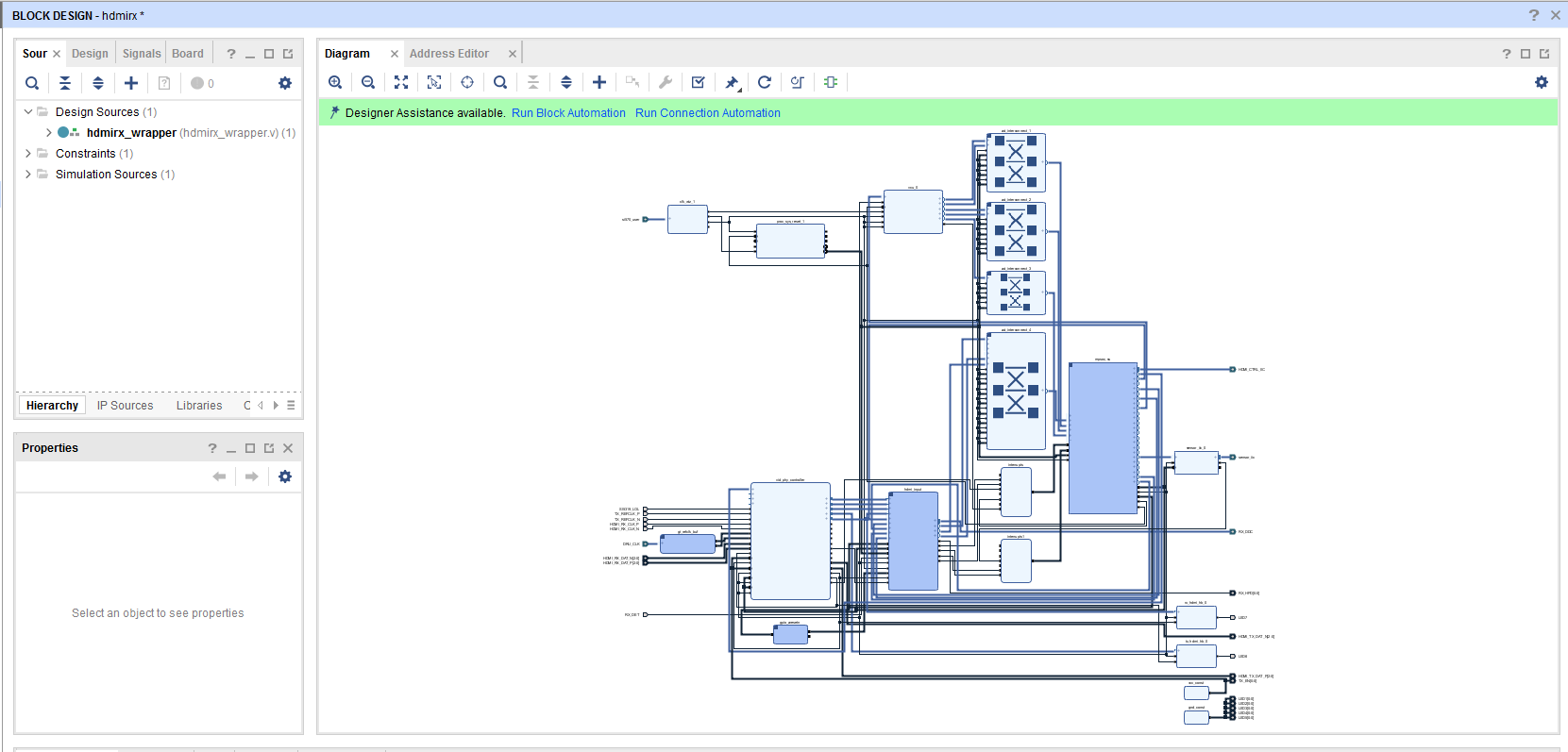
- Click on “Generate Bitstream”.
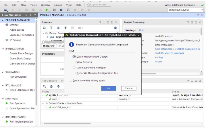
Note: If the user gets any pop-up with “No implementation Results available”. Click “Yes”. Then, if any pop-up comes up with “Launch runs”, Click "OK”.
The design is implemented and a pop-up window comes up saying “Open Implemented Design”. Click "OK".
After opening implemented design, the window looks as shown in the below figure.
Note: The actual results might graphically look different than the image shown

- Go to File > Export > Export Hardware
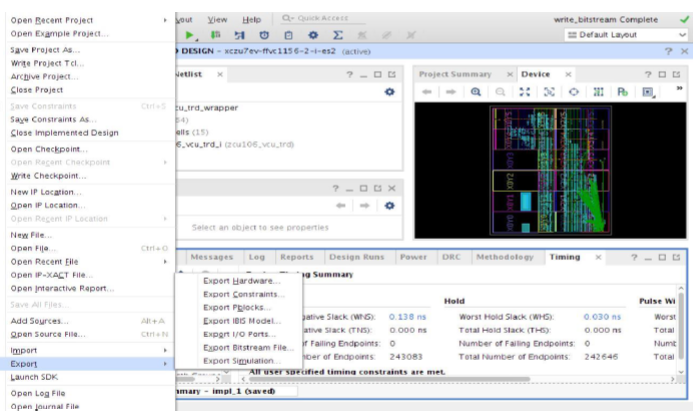
- In the Export Hardware Platform for SDK window select "Include bitstream" and click "OK".

The HDF is created at $TRD_HOME/pl\hdmirx_proj\hdmirx.sdk\hdmirx_wrapper.hdf
1.3.2 VCU PetaLinux BSP
This tutorial shows how to build the Linux image and boot image using the PetaLinux build tool.PetaLinux Installation: Refer to the PetaLinux Tools Documentation (UG1144) for installation.
% source <path/to/petalinux-installer>/Petalinux-v2018.2/petalinux-v2018.2-final/settings.sh
% echo $PETALINUX
- Configure and build the PetaLinux project for hdmirx + vcu design.
% cd $TRD_HOME/apu/vcu_petalinux_bsp
% petalinux-create -t project -s xilinx-vcu-trd-zcu106-zu7-v2018.2.bsp
% cd xilinx-vcu-trd-zcu106-zu7-v2018.2
% petalinux-config --get-hw-description=$TRD_HOME/pl/pre-built/hdmirx_vcu/
% cp project-spec/meta-user/recipes-bsp/device-tree/files/zcu106-vcu-dm1.dtsi project-spec/meta-user/recipes-bsp/device-tree/files/system-user.dtsi
% petalinux-build
NOTE:
- If Vivado project is modified, the user is expected to configure the bsp with the modified .hdf file and build.
% petalinux-config --get-hw-description=$TRD_HOME/pl/hdmirx_proj/hdmirx.sdk
- Apply the following TMDS patches (Only for rev-b board) - Edit recipes-kernel/modules/kernel-module-hdmi_%.bbappend to include 0001-Subject-PATCH-xilinx-hdmi-rx-Add-HPD-hack-for-ZCU106.patch
vi project-spec/meta-user/recipes-kernel/modules/kernel-module-hdmi_%.bbappend
SRC_URI_append = " \
                 file://0001-xilinx_drm_hdmi-Remove-unsupported-format-print-in-d.patch \
                 file://0001-Subject-PATCH-xilinx-hdmi-rx-Add-HPD-hack-for-ZCU106.patch \
"
- Build SDK components to use it as sysroot for the application development.
% petalinux-build --sdk
% petalinux-package --sysroot
- Create a boot image (BOOT.BIN) including FSBL, ATF, bitstream, and u-boot.
% cd images/linux
% petalinux-package --boot --fsbl zynqmp_fsbl.elf --u-boot u-boot.elf --pmufw pmufw.elf --fpga system.bit
- Copy the generated boot image and Linux image to the SD card directory. Replace rev-x with board revision
cp BOOT.BIN image.ub $TRD_HOME/images/vcu_trd/rev-x
Custom EDID Support
The TRD design is tested/validated with ABOX 2017 and NVIDIA SHIELD Pro. If you wants to try with any new HDMI source, you need to generate the EDID of the new source and update it in the TRD bsp. Refer to Custom EDID Support for adding the newly generated EDID file.
1.3.3 VCU APM library
This tutorial shows how to build the VCU APM library.- Set the build environment variables. This requires that you have previously completed the PetaLinux SDK installation step.
Note 2: The below command might ask you execute unset LD_LIBRARY_PATH and then re-execute the command. Go ahead and follow those steps.
% source <compiled petalinux bsp path>/images/linux/sdk/environment-setup-aarch64-xilinx-linux
- Open the SDK workspace using the Xilinx SDK tool.
% cd $TRD_HOME/apu/apps
% xsdk -workspace . &&
- From the menu bar, select File -> Import.., then select General -> Existing Projects into Workspace. Click Next.
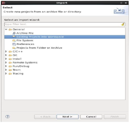
- Browse to the $TRD_HOME/apu/apps directory. Select “Deselect All” and then select vcu_apm_lib project. Click Finish.
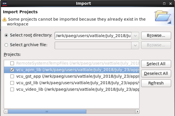
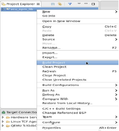
- Right-click the vcu_apm_lib project and select 'Build Project'
1.3.4 VCU Video library
This tutorial shows how to build the VCU video library.- From the menu bar, select File -> Import…, then select General -> Existing Projects into Workspace. Click Next.
- Browse to the $TRD_HOME/apu/apps directory. Select “Deselect All” and select vcu_video_lib project. Click Finish.
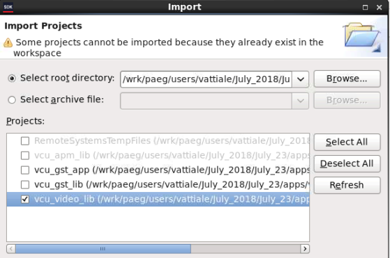
- Right-click the vcu_video_lib project and select 'Build Project'
1.3.5 VCU GST library
This tutorial shows how to build the VCU GST library.- From the menu bar, select File -> Import…, then select General -> Existing Projects into Workspace. Click Next.
- Browse to the $TRD_HOME/apu/apps directory. Select “Deselect All” and select vcu_gst_lib project. Click Finish.
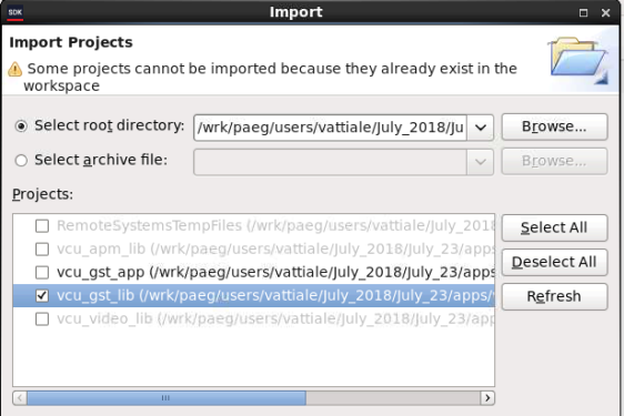
- Right-click the vcu_gst_lib project and select 'Build Project'
1.3.6 VCU GST APP
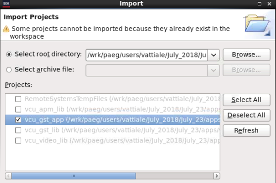
This tutorial shows how to build the VCU GST APP.- From the menu bar, select File -> Import…, then select General -> Existing Projects into Workspace. Click Next.
- Browse to the $TRD_HOME/apu/apps directory. Select “Deselect All” and select vcu_gst_app project. Click Finish.
- Right-click the vcu_gst_app project and select 'Build Project'
2 Other Information
2.1 Supported Features
The table below provides the supported encoder feature in this release.| Encoder Format | Command Line |
| Single Stream | |
| HEVC 4kp60 | √ |
| AVC 4kp60 | √ |
| HEVC 4kp30 | √ |
| AVC 4kp30 | √ |
| HEVC 1080p60 | √ |
| AVC 1080p60 | √ |
√ - Supported
x - Not supported
NA - Not applicable
3 Appendix A - Input Configuration File (input.cfg)
The example configuration files are stored at /media/card/config/ folder.Common Configuration:
It is the starting point of common configuration.
Num of Input:
Provide the number of input. that is always 1 for this design.
Output:
Select the video interface.
Options: DP
Out Type:
Options: record, and stream
Display Rate:
Pipeline frame rate.
Options: 30 FPS or 60 FPS for each pipeline.
Exit:
It indicates to the application that the configuration is over.
Input Configuration:
It is the starting point of Input configuration.
Input Num:
Starting Nth input configuration.
Options: 1
Input Type:
Input source type.
Options: HDMI
Uri:
File path. Applicable for file playback only. File path should be appended by “file:”
Options: file:///media/usb/abc.mp4//
Raw:
To tell pipeline is processed or pass-through.
Options: False
Width:
The width of the live source.
Options: 3840, 1920
Height:
The height of the live source.
Options: 2160, 1080
Exit:
It indicates to the application that the configuration is over.
Encoder Configuration:
It is the starting point of Encoder configuration.
Encoder Num:
Starting Nth encoder configuration.
Options: 1
Encoder Name:
Name of the encoder.
Options: AVC, HEVC
Profile:
Name of the profile.
Options: baseline, main or high for AVC. Main for HEVC.
Rate Control:
Rate control options.
Options: CBR, VBR, and low-latency.
Filler Data:
Filler Data NAL units for CBR rate control.
Options: True, False
QP:
QP control mode used by the VCU encoder.
Options: Uniform, Auto
L2 Cache:
Enable or Disable L2Cache buffer in encoding process.
Options: True, False
Latency Mode:
Encoder latency mode.
Options: normal, sub_frame
Low Bandwidth:
If enabled, decrease the vertical search range used for P-frame motion estimation to reduce the bandwidth.
Options: True, False
Gop Mode:
Group of Pictures mode.
Options: Basic, low_delay_p, low_delay_b
Bitrate:
Target bitrate in Kbps
Options: 1-60000
B Frames:
Number of B-frames between two consecutive P-frames
Options: 0-4
Slice:
The number of slices produced for each frame. Each slice contains one or more complete macroblock/CTU row(s). Slices are distributed over the frame as regularly as possible. If slice-size is defined as well more slices may be produced to fit the slice-size requirement.
Options:
4-22 4kp resolution with HEVC codec
4-32 4kp resolution with AVC codec
4-32 1080p resolution with HEVC codec
4-32 1080p resolution with AVC codec
GoP Length:
The distance between two consecutive I frames
Options: 1-1000
Format:
The format of input data.
Options: NV12
Preset:
Options: HEVC_HIGH, HEVC_MEDIUM, HEVC_LOW, AVC_HIGH, AVC_MEDIUM, AVC_LOW, Custom
Exit
It indicates to the application that the configuration is over.
Record Configuration:
It is the starting point of Record configuration.
Record Num:
Starting Nth record configuration.
Options: 1.
Out-File Name:
Record file path.
Options: /media/usb/abc.mp4
Duration:
Duration in minutes.
Options: 1-3
Exit
It indicates to the application that the configuration is over.
Streaming Configuration:
It is the starting point of streaming configuration.
Streaming Num:
Starting Nth Streaming configuration.
Options: 1.
Host IP:
The host to send the packets to
Options: 192.168.25.89, Window PC IP.
Port:
The port to send the packets to
Options: 5004,5008,5012 and 5016.
Exit
It indicates to the application that the configuration is over.
Trace Configuration:
It is the starting point of trace configuration.
FPS Info:
To display fps info on the console.
Options: True, False
APM Info:
To display APM counter number on the console.
Options: True, False
Pipeline Info:
To display pipeline info on console.
Options: True, False
Exit
It indicates to the application that the configuration is over.
4 Appendix B
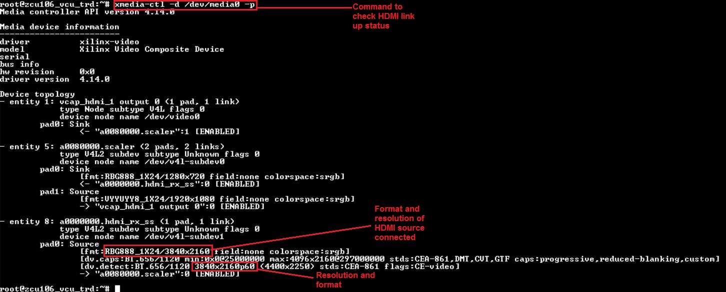
Steps for GStreamer command line execution:Support for only Single stream playback from the command line is available in this release.
- Run the below command to check HDMI link status and output format of the HDMI input source
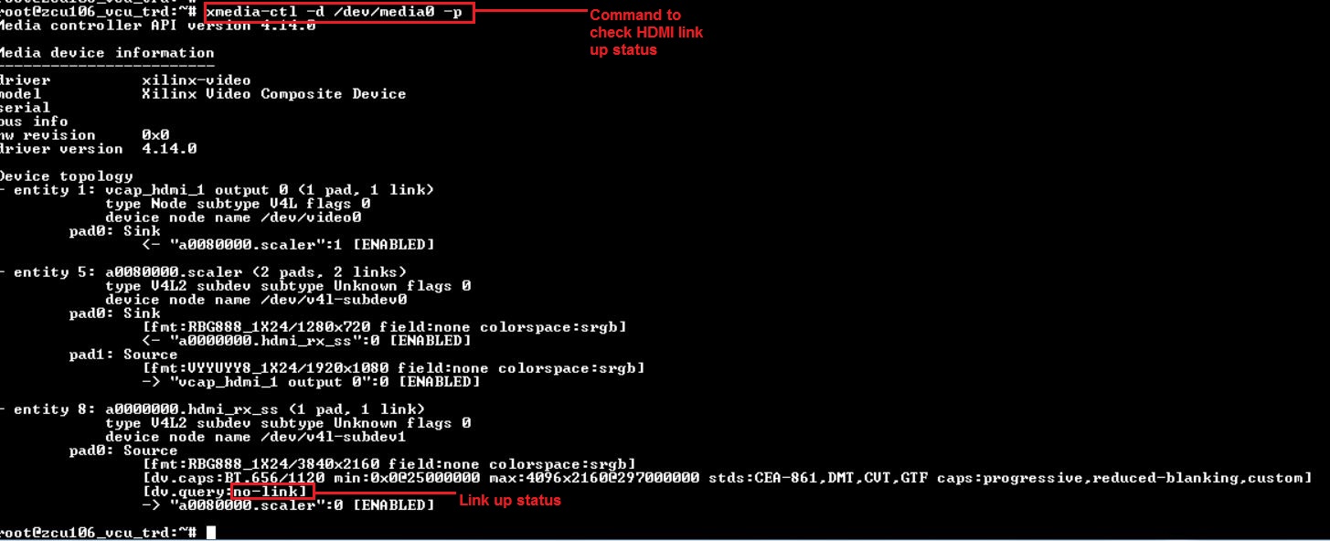
If HDMI-Rx link has issue, it appears as below.
© Copyright 2019 - 2022 Xilinx Inc. Privacy Policy