Zynq 7000 Partial Reconfiguration Reference Design
This wiki page complements XAPP1159.
Table of Contents
1 Introduction
This tutorial shows how to develop a Partial Reconfiguration (PR) design for the Zynq-7000 SoC using the Xilinx Platform Studio (XPS), Software Development Kit (SDK), and PlanAhead design tools. It complements application note XAPP1159 which focuses on conceptual aspects of the PR flow and Zynq architecture specific design considerations.
1.1 Design Overview
The PR reference design is built on top of the ZC702 Base Targeted Reference Design (TRD) , an embedded video processing application that demonstrates how it is best to separate control and data processing functions. In this example a compute-intensive video filtering algorithm is moved from the Processing System (PS) onto a hardware accelerator in Programmable Logic (PL). The video filter IP core demonstrated in the ZC702 Base TRD is a Sobel filter configured with edge detection coefficients which has been generated using the High-Level Synthesis tool Vivado HLS. For this reference design, a second video filter IP core (Sepia filter) was generated again using Vivado HLS. The provided reference design demonstrates how to use software-controlled Partial Reconfiguration (PR) to dynamically reconfigure part of the PL with the desired video filter IP core and observe the video output on a monitor.
1.2 Requirements
Software
- ISE Design Suite v14.4 Embedded or System Edition
- Vivado HLS v2012.4 to generate video filter IP cores (optional).
- Silicon Labs CP210x USB to UART Bridge VCP Driver (only required when using standalone boot image).
- Terminal emulator software, for example TeraTerm (only required when using standalone boot image).
- Linux development PC with the ARM GNU cross compile tool chain and the Git tool installed (only required for completing Sections 5 and 6.5).
Hardware
- ZC702 Evaluation Kit to run the PR reference design in hardware.
- Monitor with HDMI or DVI port that supports 1080p60 video resolution.
- Avnet FMC-IMAGEON module and external video source that provides 1080p60 video input over HDMI (optional).
- USB hub, USB mouse, and USB keyboard (only required when using Linux boot image).
Licensing
- Xilinx Vivado HLS: A 30-day evaluation license can be generated after registering a Xilinx account.
- Xilinx ISE Design Suite System Edition: A 30-day evaluation license can be generated after registering a Xilinx account.
- Xilinx Partial Reconfiguration is a product inside the ISE Design Suite that requires a license. 30-day evaluation licenses are available through the Xilinx University Program (XUP).
- Xilinx IP evaluation licenses for the Video Timing Controller and Chroma Resampler IP cores can be ordered online.
- Xylon logiCVC-ML is shipped as evaluation IP core that does not require a license. License options are listed on the Xylon logiCVC-ML product site.
Note: The provided logiCVC evaluation IP core has a 1 hour timeout built-in such that the display freezes after the timer expires. The pre-generated netlists are built from this evaluation IP core so the user can implement the design without having to purchase a license. The pre-built bitfiles and boot images are built from a full logiCVC IP core and don't expire.
1.3 Directory Structure
Download and unzip the reference design archive file xapp1159.zip to a local directory. The directory structure is:
- zc702_pr_rd -- Top-level directory
- doc -- Readme file
- hw -- Hardware sources
- base_trd_prj -- Pre-configured Base TRD PlanAhead project
- hls_sepia_prj -- Sepia filter Vivado HLS project
- hls_sobel_prj -- Sobel filter Vivado HLS project
- pr_prj -- Pre-configured PR PlanAhead project
- sd -- SD card images
- linux -- Linux boot image, kernel, devicetree, ramdisk, executables, partial binaries
- standalone -- Standalone boot image, partial binaries
- sw -- Software sources
- boot -- Zynq boot image sources
- linux -- Linux boot image sources
- standalone -- Standalone boot image sources
- patch -- Linux kernel patch
- repo -- SDK standalone user repository
- drivers -- SDK standalone user drivers
- sw_services -- SDK standalone user software services
- workspace -- SDK workspace/projects
- filter_cmd -- Linux command line software application
- filter_qt -- Linux Qt-GUI software application
- filter_std -- Standalone software application
- hw_platform -- Hardware platform information
- standalone_bsp -- Bare-metal board support package
- zynq_fsbl -- First stage boot loader
- boot -- Zynq boot image sources
1.4 Known Issues
License error when using pre-synthesized logiCVC netlist
The provided pre-synthesized netlist for the logiCVC IP core (zc702_pr_rd/hw/pr_prj/zynq_pr_rd.srcs/sources_1/system_logicvc_0_wrapper.ngc) was generated from the full license core. Unless you posses a full license for this core, your implementation run will error out with the following message:
[Netlist 29-57] IP License required for netlist cell 'system_logicvc_0_wrapper', instantiated as 'system_i/LOGICVC_0'.
WARNING:Security:141 - No 'Source' license available for 'ip_xap_349logicvcml_TDP' version '1.0' (-5).
WARNING:Security:141 - No 'Bought' license available for 'ip_xap_349logicvcml_TDP' version '1.0' (-5).
WARNING:Security:141 - No 'Hardware_Evaluation' license available for 'ip_xap_349logicvcml_TDP' version '1.0' (-5).
WARNING:Security:141 - No 'Design_Linking' license available for 'ip_xap_349logicvcml_TDP' version '1.0' (-5).
ERROR:Security:142 - No IP Core license of type 'Design_Linking' or greater available for 'ip_xap_349logicvcml' version '1.0'.
Please replace the netlist with the one attached or run Section 3 first followed by Sections 4.1 through 4.9. In Section 3 you will generate a netlist from the evaluation logiCVC pcore which you will then import into the PlanAhead PR project in Section 4.1.
Image tearing
Occasional horizontal image tearing can be observed when the sobel or sepia filter engines are enabled.
2 Vivado HLS Flow
Vivado HLS provides a tool and methodology for migrating algorithms coded in C, C++ or System-C from the Zynq PS onto the PL by generating RTL code. The Sobel filter IP core used in the Zynq Base TRD was generated using this approach. Similarly, the Sepia filter IP core can be generated based on the provided C-algorithm and Vivado HLS project. The following tutorial is based on XAPP890 and shows how to implement the Sobel filter HLS project -- the same methodology can be used for the Sepia filter HLS project.
Shortcut: Pre-generated Sobel and Sepia filter IP cores are available at zc702_pr_rd/hw/base_trd_prj/zynq_base_trd.srcs/sources_1/edk/xps_proj/pcores/sepia_filter_top_v1_04_a and zc702_pr_rd/hw/base_trd_prj/zynq_base_trd.srcs/sources_1/edk/xps_proj/pcores/sobel_filter_top_v1_04_a.
2.1 Synthesizing the HLS Design
Tutorial
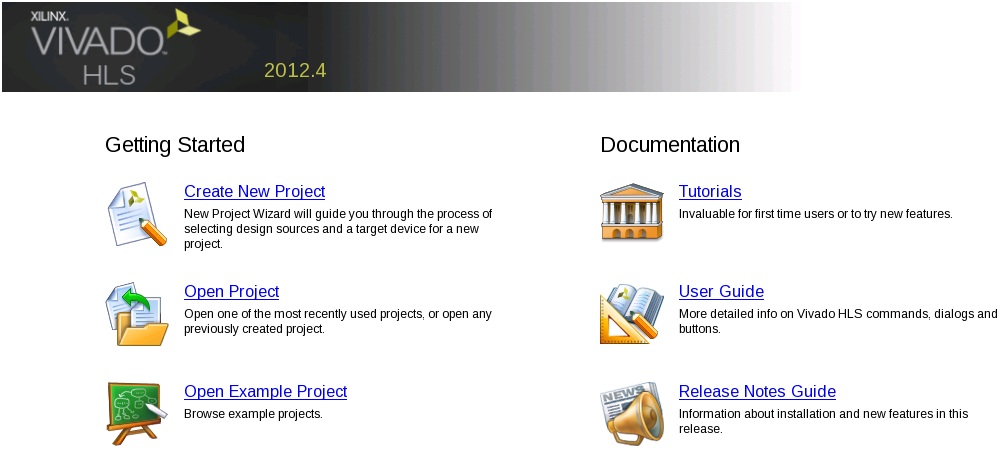
- To open Vivado HLS, select Start > All Programs > Xilinx Design Tools > Vivado 2012.4 > Vivado HLS.
- On the Vivado HLS welcome screen, click Open Project under the Getting Started group.
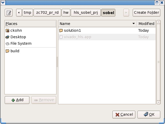
- In the Open Project dialog, browse to the zc702_pr_rd/hw/hls_sobel_prj/sobel directory and click OK.
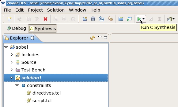
- From the icon bar, click the Synthesis button to generate the RTL for the algorithm.
2.2 Exporting the RTL as EDK Pcore
Tutorial
- Click the Export RTL button to package the RTL as EDK Pcore.
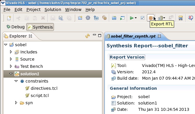
- In the dialog box, select Pcore for EDK.
- Click the Configuration... button.
- Enter 1.04.a for the pcore Version and confirm with OK twice.

- The Pcore is located in the directory zc702_pr_rd/hw/hls_sobel_prj/sobel/solution1/impl/pcores.
Repeat Sections 2.1 and 2.2 for the Sepia filter HLS project located at zc702_pr_rd/hw/hls_sepia_prj.
3 PlanAhead Base TRD Flow
The Base TRD hardware design is a PlanAhead project with an embedded XPS project. The default video filter used in the design is a Sobel filter. First you will synthesize the Base TRD with the Sobel filter using PlanAhead. Then, you will replace the Sobel filter with a Sepia filter in XPS and re-run synthesis. The generated netlists will be used as starting point for the PlanAhead PR project (see Section 4). Finally, you will export the hardware platform information so it can be imported into SDK at a later point (see Section 6.1).
Shortcut: Pre-generated netlists are available inside the PlanAhead PR project zc702_pr_rd/hw/pr_prj. A pre-configured Hardware Platform Specification is available at zc702_pr_rd/sw/workspace/hw_platform.
3.1 Synthesizing the Design
Tutorial
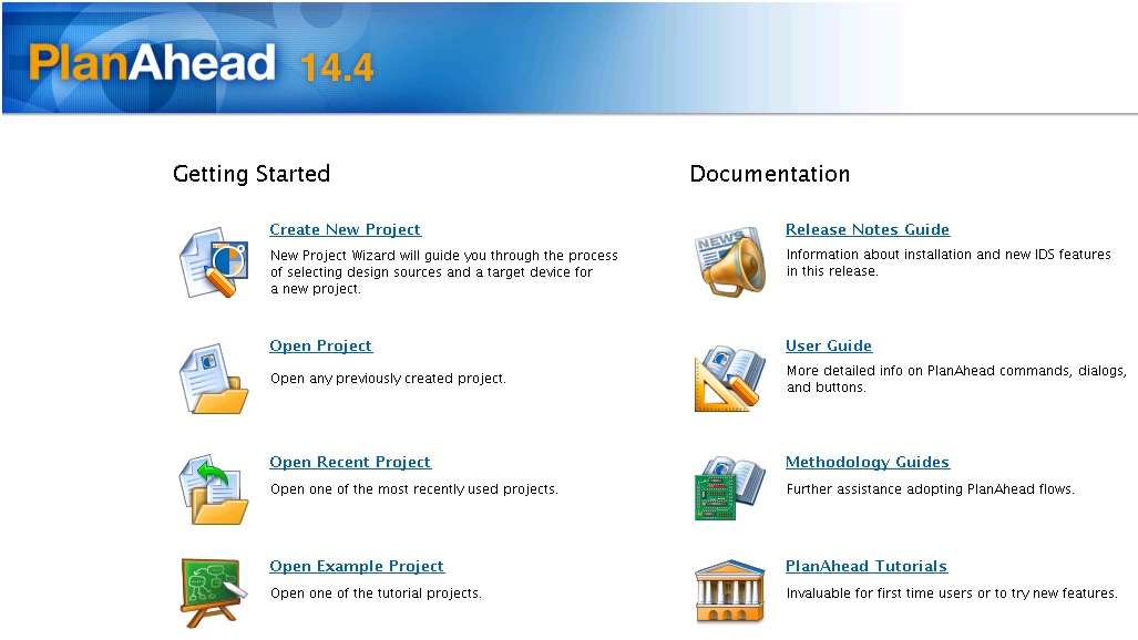
- To open PlanAhead, select Start > All Programs > Xilinx Design Tools > ISE Design Suite 14.4 > PlanAhead > PlanAhead.
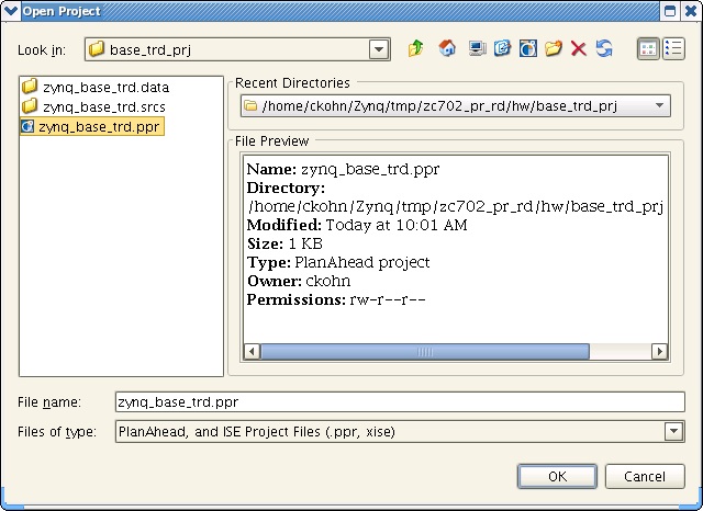
- On the PlanAhead welcome screen, click Open Project under the Getting Started group.

- In the Open Project dialog, select the zynq_base_trd.ppr project file.
- Click OK.
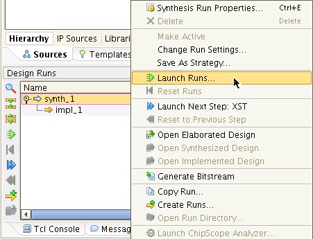
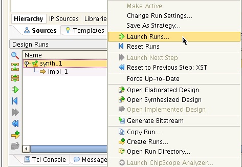
- In the Design Runs window at the bottom, right-click synth_1 and select Launch Runs....
- Click OK in Launch Selected Runs dialog.
- Click Cancel in the Synthesis Completed dialog.
- Browse to the zc702_pr_rd/hw/base_trd_prj/zynq_base_trd.srcs/sources_1/edk/xps_proj/implementation directory and rename the file system_filter_engine_wrapper.ngc to system_filter_sobel_wrapper.ngc.
3.2 Replacing the Filter and Re-Synthesizing the Design
Tutorial
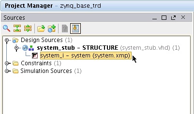
- Double-click the system_i - system (system.xmp) file in the Sources tab of Project Manager to open the embedded XPS project.
- In XPS, select the Project tab on the left and double-click MHS File: system.mhs.
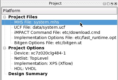
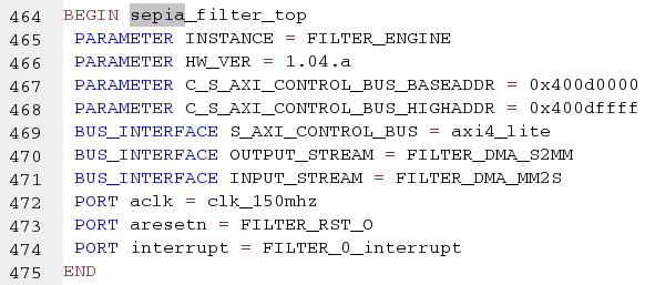
- Scroll down or search for sobel_filter_top and replace with sepia_filter_top.
- From the menu bar, select File > Save and click Reload when prompted to reload the project.
- Close XPS and click Yes when prompted to continue to exit XPS.
- Back in PlanAhead, select the Design Runs tab at the bottom.
Note: The synth_1 run has a yellow exclamation mark sign on top of a green check mark next to it, indicating that the synthesis run is completed but out-of-date. This is because we have modified the XPS project by replacing the Sobel Filter with a Sepia filter. - Right-click synth_1 and select Launch Runs....
- Click OK twice.
- Click Cancel in the Synthesis Completed dialog.
- Browse to the zc702_pr_rd/hw/base_trd_prj/zynq_base_trd.srcs/sources_1/edk/xps_proj/implementation directory and rename the file system_filter_engine_wrapper.ngc to system_filter_sepia_wrapper.ngc.
3.3 Exporting the Hardware Platform Specification
Tutorial
- From the menu bar, select File > Export > Export Hardware for SDK...
- Click OK.
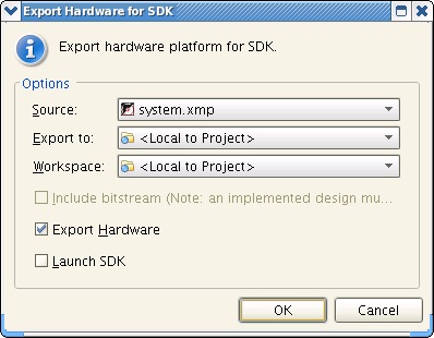
- The generated Hardware Platform Specification is located at zc702_pr_rd/hw/base_trd_prj/zynq_base_trd.sdk/SDK/SDK_Export/hw
4 PlanAhead Partial Reconfiguration Design Flow
Based on the synthesized netlists from the Base TRD hardware design, you will use the PlanAhead tool to create a reconfigurable partition, floorplan the design, add reconfigurable modules, run the implementation tools, and generate full and partial bitstreams. The promgen tool is used to convert the partial bitstreams to binary format so they can be used by the software application to configure the PL through the PCAP port.
Shortcut 1: A pre-built full bitstream (sobel configuration) is available at zc702_pr_rd/sw/boot/*/sobel.bit. Partial Sobel and Sepia bitstreams are available at zc702_pr_rd/sd/*/sobel.bin and zc702_pr_rd/sd/*/sepia.bin.
Shortcut 2: A pre-configured PlanAhead PR project is available at zc702_pr_rd/hw/pr_prj. When using this project, only the last two steps in the PR flow -- implementation and bitstream generation -- need to be run (see tutorial below).
Tutorial
- To open PlanAhead, select Start > All Programs > Xilinx Design Tools > ISE Design Suite 14.4 > PlanAhead > PlanAhead.
- On the PlanAhead welcome screen, click Open Project under the Getting Started group.

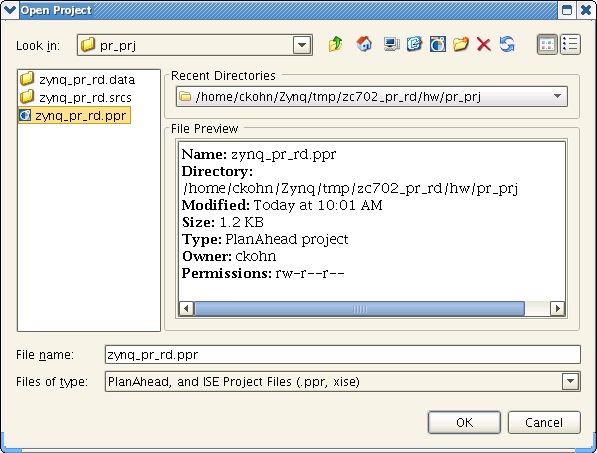
- In the Open Project dialog, browse to the zc702_pr_rd/hw/pr_prj directory and select zynq_pr_rd.ppr.
- Click OK.
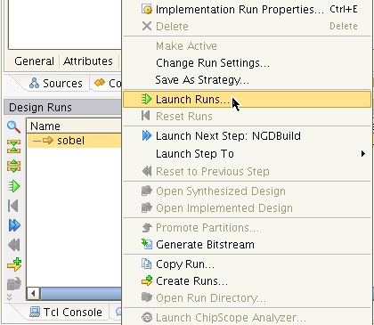
- In the Design Runs window at the bottom, right-click sobel and select Launch Run....
- Click OK in the Launch Selected Runs dialog.
- Click OK in the Launch Runs Critical Messages dialog to ignore the warnings.
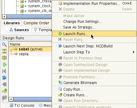
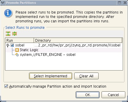
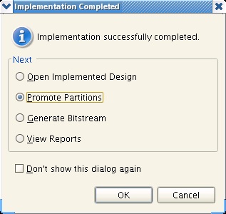
- In the Implementation Completed dialog, select Promote Partitions.
- Click OK twice.

- Click OK in the Promote Partitions dialog.
- Click OK in the Critical Messages dialog.
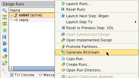
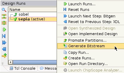
- Select the sobel run, right-click and select Generate Bitstream.
- Click OK.
- Repeat steps 5 through 13 for the sepia run, except in the Implementation Completed dialog, click Cancel.
- Select the Tcl Console tab at the bottom.
- At the command line prompt, enter exec promgen -b -w -p bin -data_width 32 -u 0 zynq_pr_rd.runs/sobel/sobel_system_i_FILTER_ENGINE_sobel_partial.bit -o zynq_pr_rd.runs/sobel/sobel.bin to convert the partial sobel bitfile to binary format.
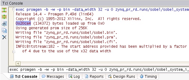
- Next, enter exec promgen -b -w -p bin -data_width 32 -u 0 zynq_pr_rd.runs/sepia/sepia_system_i_FILTER_ENGINE_sepia_partial.bit -o zynq_pr_rd.runs/sepia/sepia.bin to convert the partial sepia bitfile to binary format.
- Note down the size of the generated partial binary files as indicated by the promgen console output -- the file size should be identical for both partial binaries.
Alternatively, complete Sections 4.1 through 4.9 for the full PR design flow tutorial.
4.1 Creating a PR Project and Importing the Generated Netlists
Tutorial
- Create a new directory zc702_pr_rd/hw/pr_prj_lab for this tutorial.
- To open PlanAhead, select Start > All Programs > Xilinx Design Tools > ISE Design Suite 14.4 > PlanAhead > PlanAhead.
- On the PlanAhead welcome screen, click Create New Project under the Getting Started group.
- Click Next.
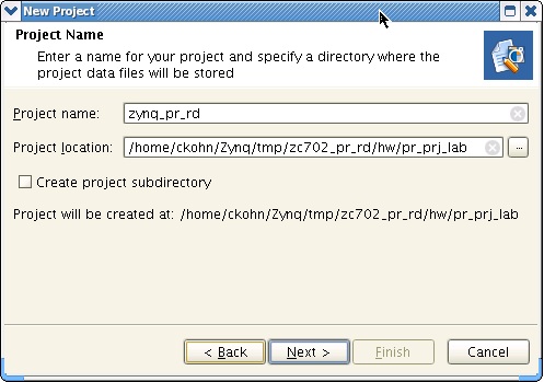
- In the Project Name dialog, change the Project name to zynq_pr_rd.
- Browse to the zc702_pr_rd/hw/pr_prj_lab directory for Project location and click Select.
- Click Next.
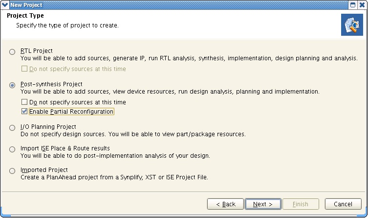
- In the Project Type dialog, select Post-synthesis Project and check the Enable Partial Reconfiguration box.
- Click Next.
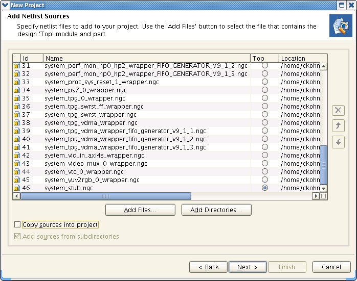
- In the Add Netlist Sources dialog, click the Add Files... button.
- Browse to the zc702_pr_rd/hw/base_trd_prj/zynq_base_trd.srcs/sources_1/edk/xps_proj/implementation directory.
- Select all .ngc files except for system_filter_sepia_wrapper.ngc and system_filter_sobel_wrapper.ngc and click OK.
- Click the Add Files... button again.
- Browse to the zc702_pr_rd/hw/base_trd_prj/zynq_base_trd.runs/synth_1 directory.
- Select system_stub.ngc and click OK.
- Mark system_stub.ngc as top-level module by checking the radio button in the Top column next to the file name.
- Click Next.
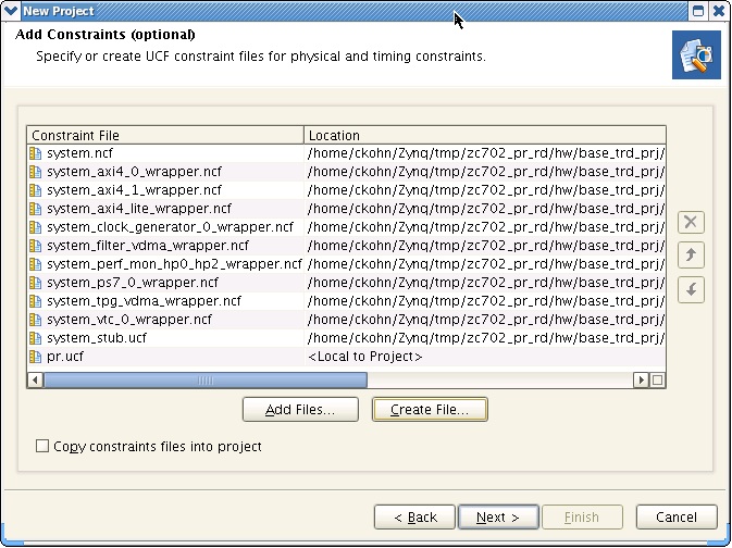
- In the Add Constraints (optional) dialog, click the Add Files... button.
- Browse to the zc702_pr_rd/hw/base_trd_prj/zynq_base_trd.srcs/sources_1/edk/xps_proj/implementation directory.
- Select all .ncf files and click OK.
- Click the Add Files... button again.
- Browse to the zc702_pr_rd/hw/base_trd_prj/zynq_base_trd.srcs/constrs_1 directory.
- Select system_stub.ucf and click OK.
- Click the Create File... button.
- Enter pr in the File name field and click OK.
- Click Next.
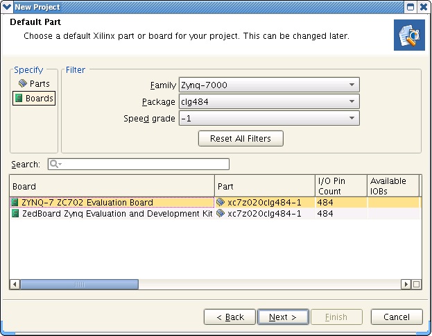
- In the Default Part dialog, select Boards.
- Select Zynq-7000 for Family, CLG484 for Package, and -1 for Speed grade.
- Select ZYNQ-7 ZC702 Evaluation Board from the bottom view.
- Click Next.
- Click Finish.
4.2 Defining a Reconfigurable Partition
Tutorial
- From the menu bar, select Flow > Open Synthesized Deign.
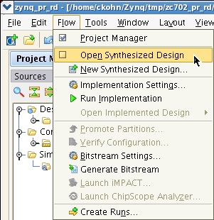
- The Undefined Modules Found and the Critical Messages windows can be ignored. Click OK twice.
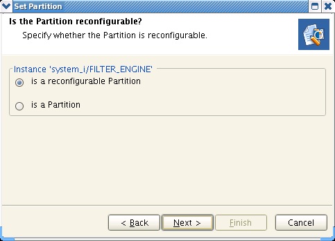
Note: The missing netlist refers to the block that will be our reconfigurable module and hence marked as black box for now. - In the Netlist view of Synthesized Design, right-click the FILTER_ENGINE module and select Set Partition....
- Click Next.
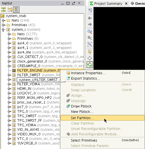
- In the Set Partition dialog, select is a reconfigurable Partition.
- Click Next.
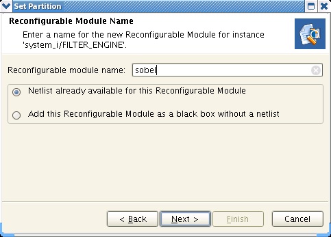
- Enter sobel for Reconfigurable Module Name and select Netlist already available for this Reconfigurable Module.
- Click Next.
- For Top netlist file, browse to the zc702_pr_rd/hw/base_trd_prj/zynq_base_trd.srcs/sources_1/edk/xps_proj/implementation directory, select the file system_filter_sobel_wrapper.ngc and click OK.
- Click Next.

- Skip the Add Constraints dialog and click Next.
- Click Finish.
- The Netlist view is updated showing a diamond next to the FILTER_ENGINE module and the entry sobel under Reconfigurable Modules.
Note: The check mark inside the diamond next to sobel indicates that this module is the currently active reconfigurable module.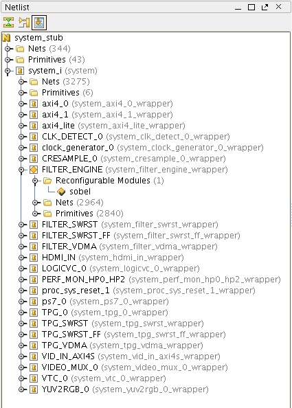
4.3 Adding a Reconfigurable Module
Tutorial
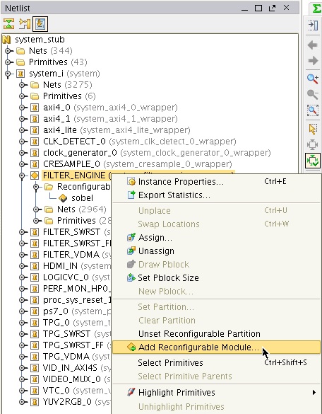
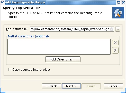
- In the Netlist view of Synthesized Design, right-click the FILTER_ENGINE module and select Add Reconfigurable Module....
- Click Next.
- Enter sepia for Reconfigurable Module Name and select Netlist already available for this Reconfigurable Module.
- Click Next.

- Browse to the zc702_pr_rd/hw/base_trd_prj/zynq_base_trd.srcs/sources_1/edk/xps_proj/implementation directory, select system_filter_sepia_wrapper.ngc and click OK.
- Click Next.
- Skip the Add Constraints dialog and click Next.
- Click Finish.
- The Netlist view is updated showing the entry sepia under Reconfigurable Modules.
Note: The sepia module does not have a check mark inside the diamond next to it since there can be only one active reconfigurable module.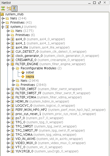
4.4 Floorplanning the Reconfigurable Partition
Tutorial
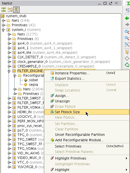
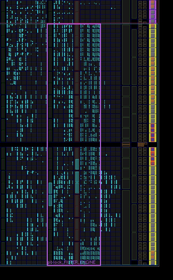
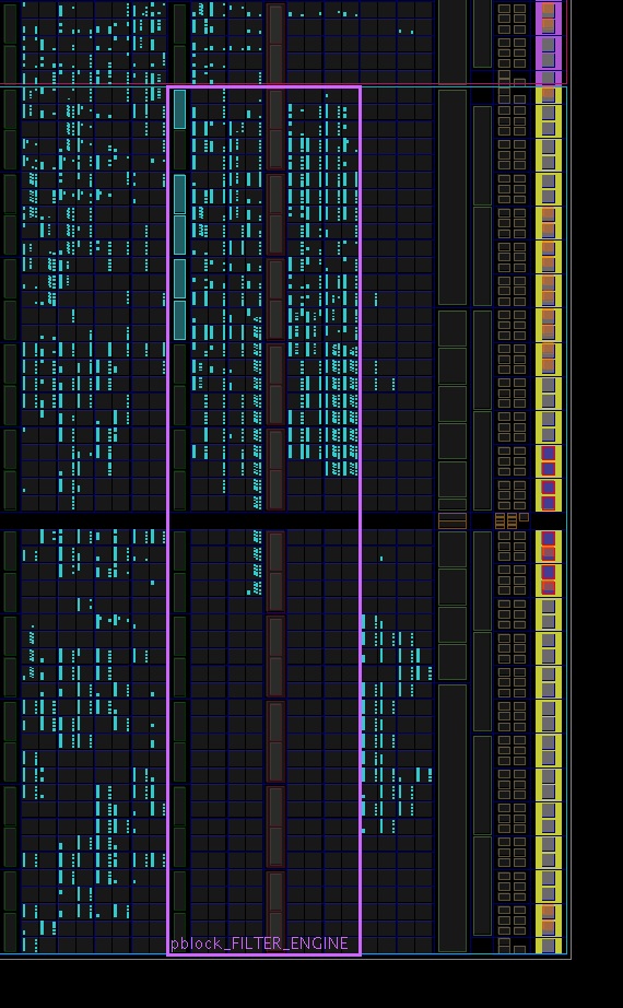
- In the Netlist view of Synthesized Design, right-click the FILTER_ENGINE module and select Set Pblock Size.
- In the Device window, zoom into clock region X1Y0 at the bottom right.
- Click and drag the mouse cursor to draw a box that bounds SLICE_X102Y0:SLICE_X109Y49 (bottom left to top right) as shown in the figure.
Note: Inside the Pblock, the blue rectangles denote Slices, the column of green rectangles on the left denote DSPs, the column of orange/red rectangles on the right denote BRAMs.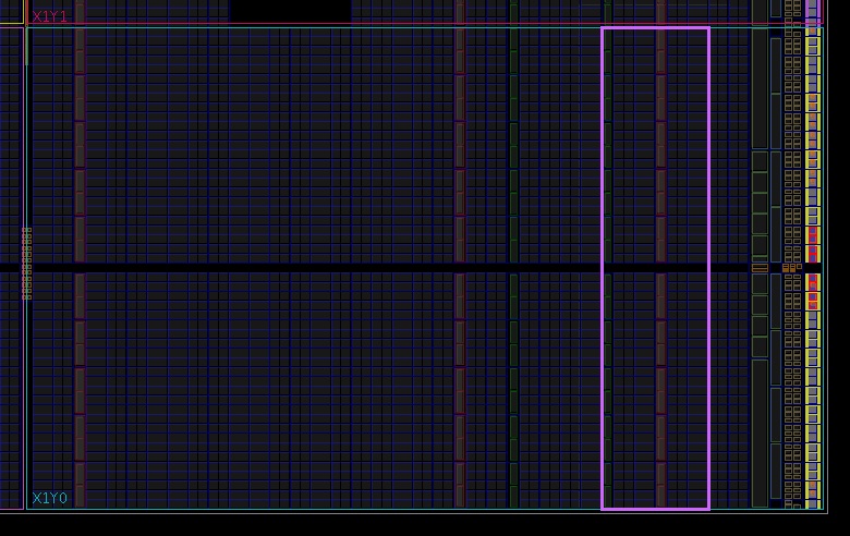
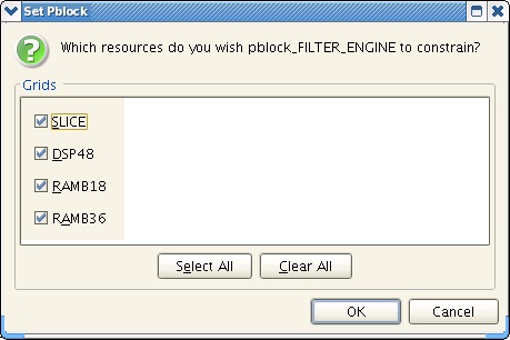
- In the Set Pblock dialog, make sure that all of SLICE, DSP48, RAMB18, and RAMB36 are checked.
- Click OK.
- In the Device window, select the previously drawn Pblock such that it is highlighted, then right-click and select Pblock Properties....
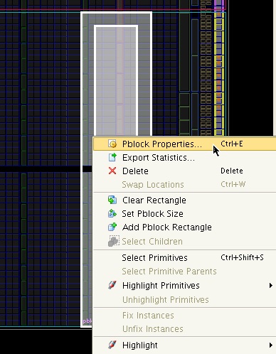
- In the Pblock Properties window, select the Statistics tab. In the Physical Resource Estimates section, check that the utilization for the various site types is lower than 100%. We have now verified that the drawn Pblock is big enough to hold the sobel reconfigurable module.

- In the Netlist view of Synthesized Design, right-click the sepia reconfigurable module and select Set as Active Reconfigurable Module.
- Click Save when prompted to save the Synthesized Design.
Note: This will save the area group constraints for the created Pblock to the constraints file.
- Repeat steps 5 and 6 to pull up the Pblock Properties window and check the utilization for the sepia reconfigurable module. How does it compare to the sobel reconfigurable module in terms of required LUTs, DSPs, and BRAMs?

4.5 Creating, Implementing, and Promoting the Sobel Configuration
Tutorial
- Select the Design Runs tab at the bottom of the screen.
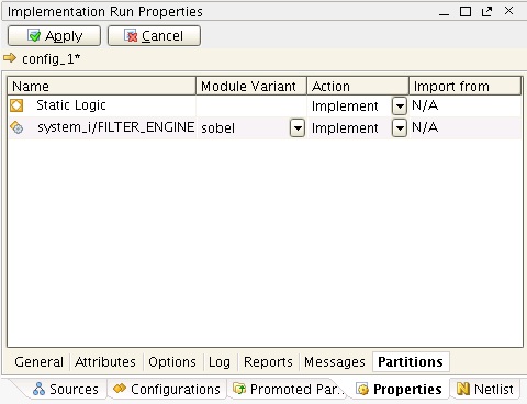
- Right-click config_1 and select Implementation Run Properties....
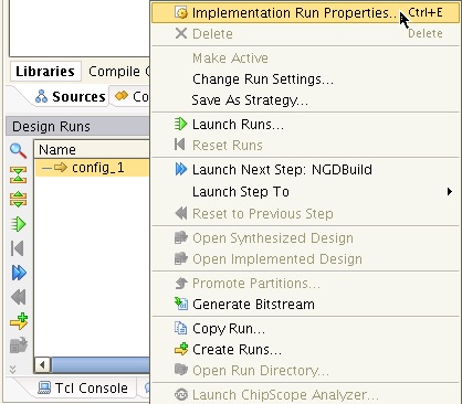
- In the Properties window, select the General tab and change Name to sobel.
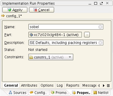
- In the Partitions tab, make sure that sobel is selected under Module Variant and Implement under Action.
- Click Apply to save the changes.
- Back in the Design Runs tab at the bottom, right-click sobel and select Launch Runs...
- Click OK.
- Click OK in the Launch Run Critical Messages dialog to ignore the warnings.
- In the Implementation Completed dialog, select Promote Partitions.
- Click OK twice.
- Optional: To open the implemented design, select Flow > Open Implemented Design > sobel from the menu bar and examine the routed design in the Device window. How does it compare to the post-synthesis physical resources estimates?
4.6 Creating and Implementing the Sepia Configuration
Tutorial
- In the Design Runs window at the bottom, right-click into the empty space and select Create Runs....
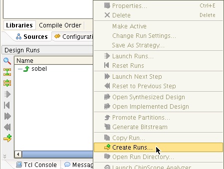
- Click Next.
- In the Create Implementation Runs dialog, change Name to sepia.
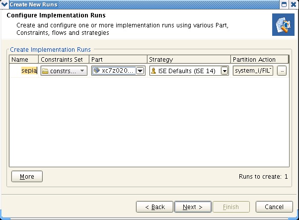
- Click the ... icon under Partition Action.
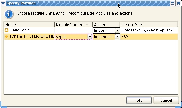
- In the Specify Partition dialog, select sepia under Module Variant and Implement under Action.
- Make sure that for Static Logic, Action is set to Import.
Note: This will import the static logic from the promoted sobel design run instead of re-implementing it. - Click OK.
- Click Next.
- In the Launch Options dialog, select Launch runs on local host.
- Click Next.
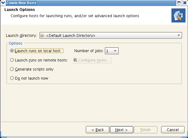
- Click Finish.
- Click OK in the Launch Run Critical Messages dialog to ignore the warnings.
- Optional: In the Implementation Completed dialog, select Open Implemented Design and examine the routed design in the Device window. How does it compare to the sepia design? How does it compare to the post-synthesis physical resources estimates?
4.7 Running the Verify Configuration Utility
Tutorial
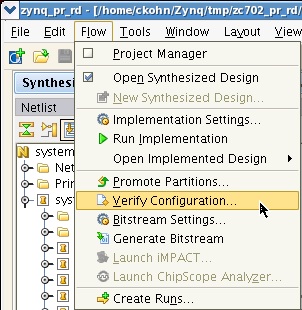
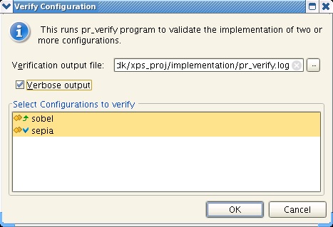
- From the menu bar, select Flow > Verify Configuration...
- Check the Verbose output box and make sure that both sobel and sepia configurations are highlighted.
- Click OK.
4.8 Generating Full and Partial Bitstreams
Tutorial
- In the Design Runs window, select the sobel run, right-click and select Generate Bitstream.
Note: The green up arrow next to sobel indicates that this run's configuration has been implemented and promoted, so its static logic can be imported by other configurations. - Click OK.
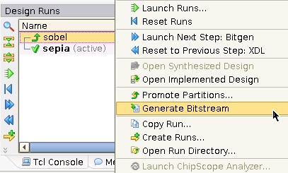
- In the Design Runs window, select the sepia run, right-click and select Generate Bitstream.
Note: The green check mark next to sepia indicates that this run's configuration has been implemented. - Click OK.
4.9 Converting Partial Bitstreams to Binary Format
Tutorial
- Select the Tcl Console tab at the bottom.
- At the command line prompt, enter exec promgen -b -w -p bin -data_width 32 -u 0 zynq_pr_rd.runs/sobel/sobel_system_i_FILTER_ENGINE_sobel_partial.bit -o zynq_pr_rd.runs/sobel/sobel.bin to convert the partial sobel bitfile to binary format.
- Next, enter exec promgen -b -w -p bin -data_width 32 -u 0 zynq_pr_rd.runs/sepia/sepia_system_i_FILTER_ENGINE_sepia_partial.bit -o zynq_pr_rd.runs/sepia/sepia.bin to convert the partial sepia bitfile to binary format.
- Note down the size of the generated partial binary files as indicated by the promgen console output -- the file size should be identical for both partial binaries.

5 Linux Components
This section describes how to build Linux specific components i.e. the second stage boot loader u-boot, the Linux kernel image and device tree blob, and the Linux root file system. To complete this section, you are required to have a Linux development PC with the ARM GNU cross compile tool chain and the Git tool installed. Make sure you have your PATH and CROSS_COMPILE environment variables set correctly. You can use the corkscrew tool if you are having difficulties accessing Xilinx git repositories from behind a firewall.
5.1 Building the u-boot Second Stage Boot Loader
This section explains how to download the sources, configure, and build the u-boot second stage boot loader. For additional information, refer to the Xilinx Zynq u-boot wiki.
Shortcut: A pre-compiled u-boot executable is available at zc702_pr_rd/sw/boot/linux/u-boot.
Tutorial
Clone the latest Zynq u-boot git repository from the Xilinx git server.
> git clone git://github.com/xilinx/u-boot-xlnx.git
> cd u-boot-xlnx
> git checkout -b zynq_pr_rd_14.4 xilinx-v14.4
> make ARCH=arm zynq_zc70x_config
> make ARCH=arm
> mv u-boot u-boot.elf
5.2 Building the Linux Kernel Image and Device Tree Blob
This section explains how to download the sources, configure, patch, and build the Linux kernel image and the device tree blob. For additional information, refer to the Xilinx Zynq Linux wiki.
Linux Kernel Image
Shortcut: A pre-compiled Linux kernel image is available at zc702_pr_rd/sd/linux/uImage.
Tutorial
Clone the latest Zynq Linux kernel git repository from the Xilinx git server.
> git clone git://github.com/xilinx/linux-xlnx.git
> cd linux-xlnx
> git checkout -b zynq_pr_rd_14.4 xilinx-v14.4
- Xilinx VDMA driver
- Xilinx Sobel/Sepia filter driver
- Zynq Base TRD config file (zynq_base_trd_defconfig)
- Zynq Base TRD device tree file (zynq_base_trd.dts)
- Mouse sensitivity patch
> cp zc702_pr_rd/sw/patch/zc702_pr_rd_14_4.patch linux-xlnx  // copy the PR RD patch
> git apply --stat zc702_pr_rd_14_4.patch                    // display contents of patch
> git apply --check zc702_pr_rd_14_4.patch                   // check if patch can be applied
> git am zc702_pr_rd_14_4.patch                              // apply the patch
> make ARCH=arm zynq_base_trd_defconfig
> make ARCH=arm uImage
Linux Device Tree Blob
Shortcut: A pre-compiled Linux device tree blob is available at zc702_pr_rd/sd/linux/devicetree.dtb.
Tutorial
Compile the Base TRD device tree file. The output of this step is a device tree blob which can be found at linux-xlnx/devicetree.dtb.
> ./scripts/dtc/dtc -I dts -O dtb -o devicetree.dtb ./arch/arm/boot/dts/zynq_base_trd.dts
5.3 Building the Linux Root File System
For instructions on how to build a Zynq Root File System, please refer to the Xilinx Zynq Root File System Creation wiki.
Note: These steps are just an example; they will not recreate the ramdisk shipped with this reference design.
Shortcut: A pre-built ramdisk image is available at zc702_pr_rd/sd/linux/uramdisk.image.gz.
At the end of the etc/init.d/rcS script, a hook was added to execute a customized user script named init.sh. Our implementation of this script is located at zc702_pr_rd/sd/linux/init.sh and takes care of the following design specific initialization:
- Mount the cross-compiled Qt/Qwt libraries image file (located at zc702_pr_rd/sd/linux/qt_lib.img)
- Create Xilinx VDMA device node
- Create Xilinx filter device node
- Auto-start the Qt GUI based software application after boot-up
To remove the auto-start feature of the Qt application, simply comment the line ./run_sobel.sh -qt inside zc702_pr_rd/sd/linux/init.sh.
6 SDK Flow
This section describes how to use SDK to compile the standalone and Linux based software applications that control the video data path and the dynamic partial reconfiguration. You will also learn how to compile the First Stage Boot Loader (FSBL) and how to create a standalone or Linux Zynq boot image. For detailed information on SDK, the Zynq boot image format and boot process, refer to UG821 .
6.1 Creating a Hardware Platform Specification
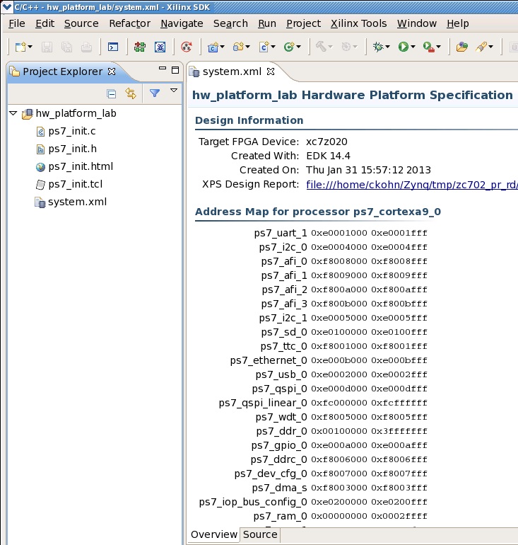
The Hardware Platform Specification is obtained by running PlanAhead's Export to SDK tool (see Section 3.3 ). It generates an XML file (system.xml) that describes the hardware system including PS and PL components and C source files that initialize the PS (ps7_init.c/h). Follow the steps below to create a Hardware Platform Specification SDK project.
Shortcut: A pre-generated Hardware Platform Specification SDK project is available at zc702_pr_rd/sw/workspace/hw_platform.
Tutorial
- To open SDK, select Start > All Programs > Xilinx Design Tools > ISE Design Suite 14.4 > EDK > Xilinx Software Development Kit.
- Browse to the zc702_pr_rd/sw/workspace directory for Workspace and click OK.
- Click OK.
- Close the welcome screen.
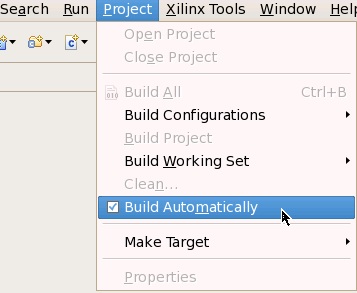
- From the menu bar, uncheck Project > Build Automatically.
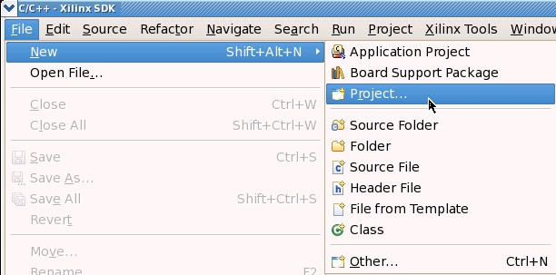
- From the menu bar, select File > New > Project.
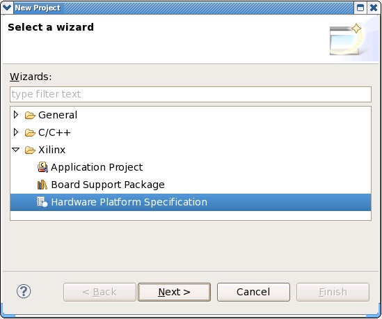
- In the New Project wizard, select Xilinx > Hardware Platform Specification.
- Click Next.
- Enter a hw_platform_lab in the Project Name field and Browse to the export location of the hardware specification file (zc702_pr_rd/hw/base_trd_prj/zynq_base_trd.sdk/SDK/SDK_Export/hw/system.xml).
- Click Finish.

- You can see the imported hardware platform files in the Project Explorer. The system.xml file contains address map information for PS and PL cores.
6.2 Generating a Board Support Package
The Board Support Package (BSP) uses the information in the Hardware Platform Specification to assign drivers to the hardware components in the design. All PS drivers and most of the PL drivers are shipped with the SDK tool suite. Custom PL drivers and software services are provided as local user repository at zc702_pr_rd/sw/repo. The BSP is linked to the main application as a library.
Shortcut: A pre-generated Board Support Package SDK project is available at zc702_pr_rd/sw/workspace/standalone_bsp.
Tutorial
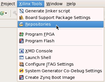
- From the menu bar, select Xilinx Tools > Repositories.
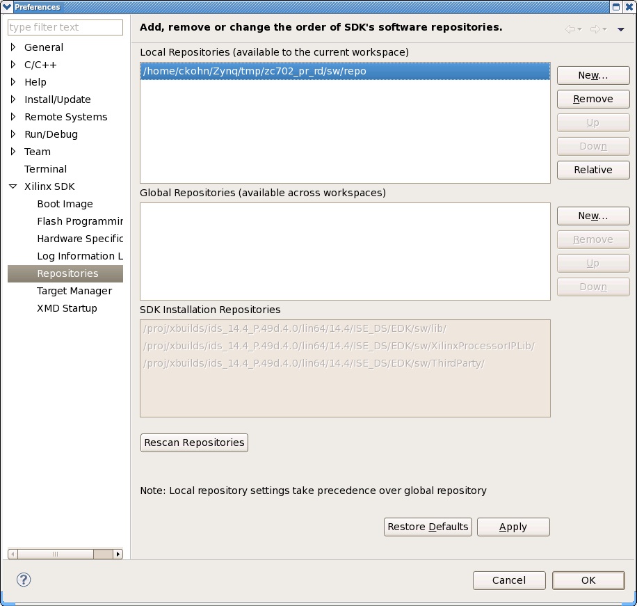
- Next to the Local Repositories text field, select New..., browse to the zc702_pr_rd/sw/repo directory, and click OK.
- Click OK.
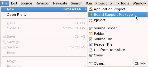
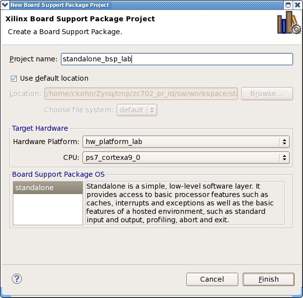
- From the menu bar, select File > New > Xilinx Board Support Package.
- Enter standalone_bsp_lab in the Project Name field and select hw_platform_lab as Hardware Platform and ps7_cortexa9_a0 as CPU.
- Click Finish.
- In the Board Support Package Settings window, select Overview on the left and check the following libraries: gpiops_adapter, iicps_adapter, sd_fatfs, and xyl_oslib. The libraries are provided in the user repository.
- Click OK.

6.3 Compiling the Standalone Software Application
Compiling the standalone or bare-metal software application for Partial Reconfiguration requires Hardware Platform Specification ( 6.1) and BSP (6.2) SDK projects. This tutorial uses the pre-generated Hardware Platform and BSP SDK projects.
Shortcut: A pre-compiled executable is available at zc702_pr_rd/sw/boot/standalone/filter_std.elf.
Tutorial
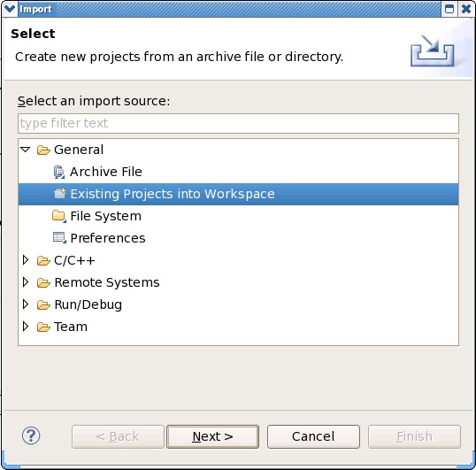
- From the menu bar, select File > Import....
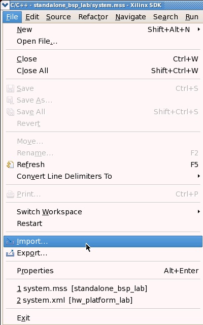
- In the Import dialog, expand the General folder, select Existing Projects into Workspace, and click Next.
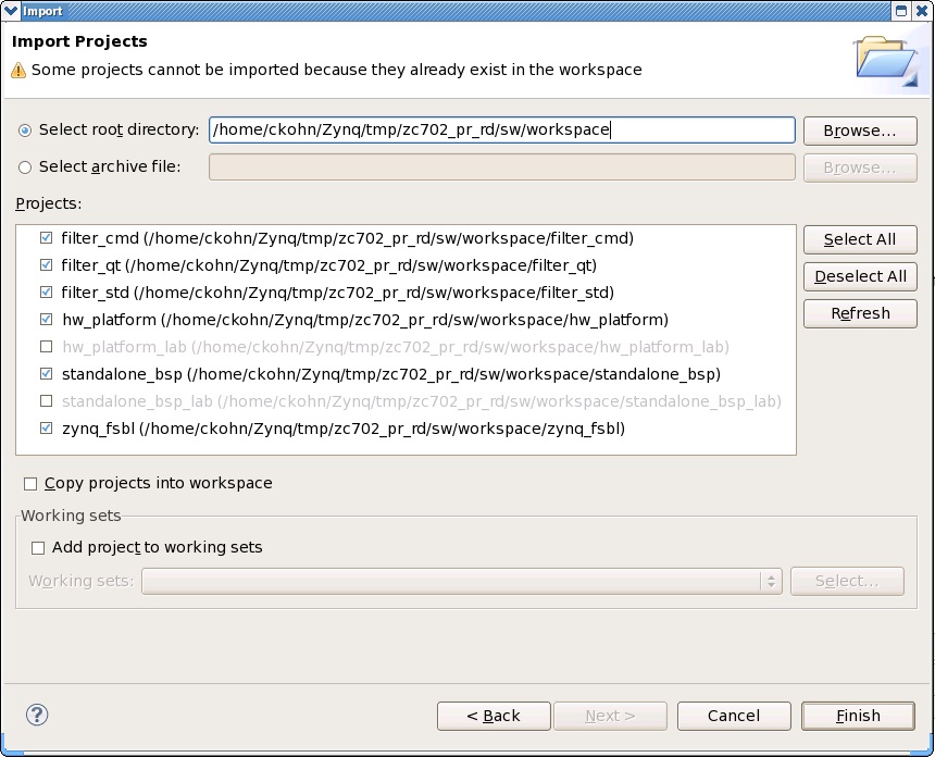
- Next to the Select root directory text field, Browse to the zc702_pr_rd/sw/workspace directory, and click OK.
- Check all projects for import. Some of them are only needed in subsequent sections.
- Click Finish.
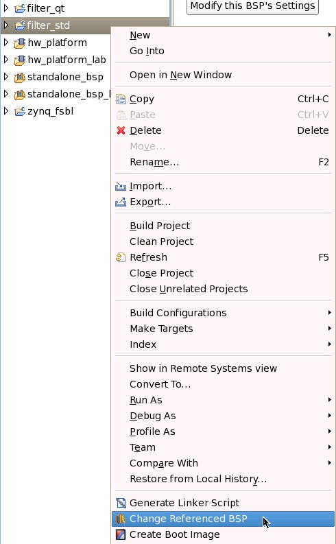
- Optional: If you want to use your own Hardware Platform Specification and BSP projects instead of the imported ones, you need to change the referenced BSP first. Right-click filter_std and select Change Referenced BSP, then select your BSP and click OK.
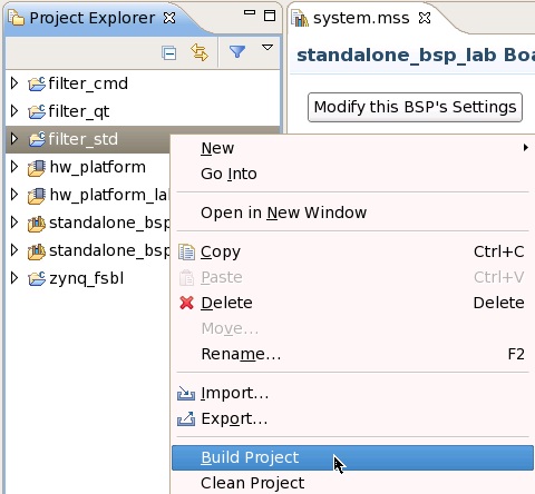
- Right-click filter_std and select Build Project.
- To change the video resolution, expand the filter_std project and open the file src/main.c. Search for the string V_1080p and change the parameter passed into the LookupVideoData_ById() function to V_720p. The corresponding data structure is defined in the file(s) src/video_common.h/c.
Note: this application supports and has been tested with 1080p and 720p video resolutions. Use any other resolution at your own risk.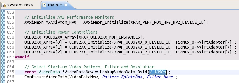
- Save the file.
- Re-compile the standalone application.
6.4 Compiling the Linux Command Line Software Application
The command line Linux software application has no dependencies on any other SDK projects and can be compiled by itself.
Shortcut: A pre-compiled executable is available at zc702_pr_rd/sd/linux/filter_cmd.
Tutorial
- This tutorial assumes that the project has already been imported into SDK (see steps in Section 6.3).
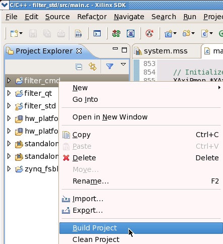
- Right-click filter_cmd and select Build Project.
6.5 Compiling the Linux Qt Software Application
The Qt Linux software application offers a GUI for navigation, built on top of the embedded Qt framework and the Qwt widget library. To complete this step, you are required to have a Linux development PC with the ARM GNU cross compile tool chain installed. For a detailed tutorial on how to build the Qt/Qwt libraries, refer to the Zynq Qt/Qwt Libraries - Build Instructions wiki. The Qt/Qwt libraries are required both, at run time and compile time. The pre-compiled Qt/Qwt image file is sufficient when executing the application on the Zynq platform. When compiling the application, in most cases you will need to recompile the Qt/Qwt libraries on your host platform since some of the generated Qt utilities are host-specific.
Shortcut: A pre-compiled Qt/Qwt libraries image file is available at zc702_pr_rd/sd/linux/qt_lib.img along with a pre-compiled executable at zc702_pr_rd/sd/linux/filter_qt. The executable also requires an images directory zc702_pr_rd/sd/linux/images/ containing data flow graphs that are displayed when the application is executed.
Tutorial
- This tutorial assumes that the project has already been imported into SDK (see steps in Section 6.3).
- Expand the filter_qt SDK project in the Project Explorer and double-click the Makefile to open it. Un-comment the highlighted line in the Makefile and set the ZYNQ_QT_INSTALL variable to your Qt/Qwt libraries installation path. Alternatively, you can create and point the ZYNQ_QT_INSTALL environment variable to your Qt/Qwt libraries installation path.
- Save the file.
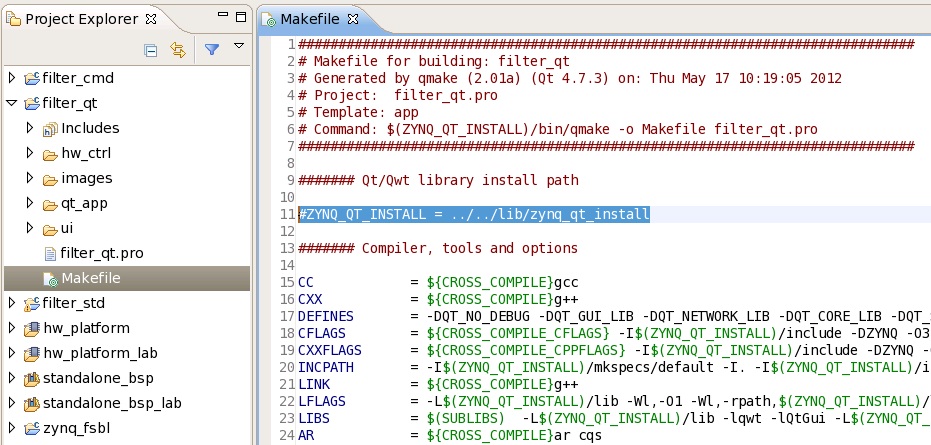
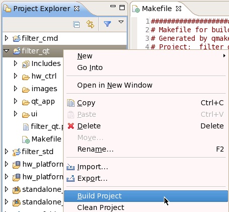
- Right-click the filter_qt project and select Build Project.
6.6 Compiling the First Stage Boot Loader
Compiling the FSBL requires Hardware Platform Specification (6.1) and BSP (6.2) SDK projects. This tutorial uses the pre-generated Hardware Platform and BSP SDK projects. The FSBL SDK project has two build configurations, one named standalone, the other named linux. The linux configuration is a customized version of the standard Xilinx FSBL which adds the following functionality:
- I2C initialization sequence for HDMI transmitter (ADV7511) on ZC702 base board
- I2C FMC-IMAGEON daughter card detection sequence
- I2C initialization sequence for HDMI receiver (ADV7611) on Avnet FMC-IMAGEON
In the standalone case, the corresponding initialization is done inside the application itself instead of the FSBL.
Shortcut: Pre-compiled FSBL executables are available at zc702_pr_rd/sw/boot/standalone/zynq_fsbl.elf and zc702_pr_rd/sw/boot/linux/zynq_fsbl.elf.
Tutorial
- This tutorial assumes that the Hardware Platform Specification, BSP, and FSBL projects have already been imported into SDK (see steps in Section 6.3).
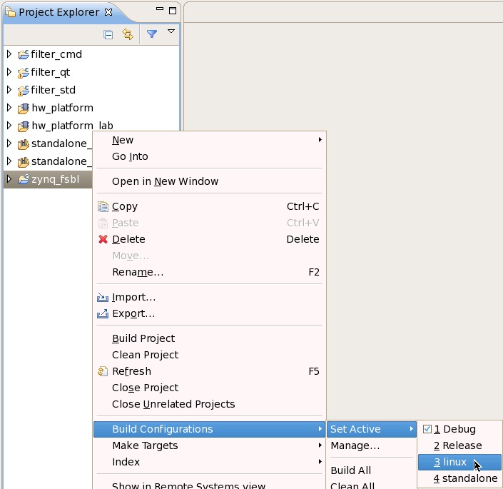
- Right-click the zynq_fsbl project and select Build Configurations > Set Active > linux.
- Optional: If you want to use your own Hardware Platform Specification and BSP projects instead of the imported ones, you need to change the referenced BSP first (see steps in Section 6.3).
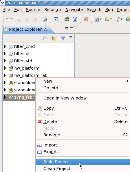
- Right-click the zynq_fsbl project and select Build Project.
- Repeat the previous two steps with the active configuration set to standalone.
6.7 Creating a Standalone Boot Image
Creating a standalone boot image requires the following components:
| zynq_fsbl.elf | FSBL - standalone configuration (6.6) |
| sobel.bit | Full bitstream - sobel configuration (4.8) |
| filter_std.elf | Standalone software application (6.3) |
All required files to build the boot image are available at zc702_pr_rd/sw/boot/standalone.
Shortcut: A pre-generated standalone boot image is available at zc702_pr_rd/sd/standalone/BOOT.bin.
Tutorial
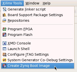
- From the menu bar, select Xilinx Tools > Create Zynq Boot Image.
- In the Create Zynq Boot Image dialog, next to the FSBL elf text field, Browse to the zc702_pr_rd/sw/boot/standalone directory, select zynq_fsbl.elf, and click OK.
- Next to the List of partitions in the boot image text field, click Add, browse to the zc702_pr_rd/sw/boot/standalone directory, select sobel.bit, and click OK.
- Click Add again, browse to the zc702_pr_rd/sw/boot/standalone directory, select filter_std.elf and click OK.
- Next to the Output folder text field, Browse to the zc702_pr_rd/sw/boot/standalone directory and click OK.
- Click Create Image.

- Navigate to the zc702_pr_rd/sw/boot/standalone directory and rename the generated boot image from filter_std.bin to BOOT.bin.
6.8 Creating a Linux Boot Image
Creating a Linux boot image requires the following components:
| zynq_fsbl.elf | FSBL - linux configuration (6.6) |
| sobel.bit | Full bitstream - sobel configuration (4.8) |
| u-boot.elf | u-boot - second stage boot loader (5.1) |
All required files to build the boot image are available at zc702_pr_rd/sw/boot/linux.
Shortcut: A pre-generated Linux boot image is available at zc702_pr_rd/sd/linux/BOOT.bin.
Tutorial
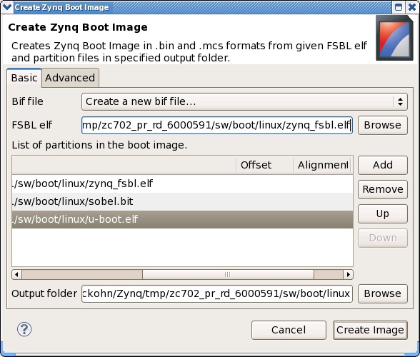
- From the menu bar, select Xilinx Tools > Create Boot Image.

- In the Create Zynq Boot Image dialog, next to the FSBL elf text field, Browse to the zc702_pr_rd/sw/boot/linux directory, select zynq_fsbl.elf, and click OK.
- Next to the List of partitions in the boot image text field, click Add, browse to the zc702_pr_rd/sw/boot/linux directory, select sobel.bit, and click OK.
- Click Add again, browse to the zc702_pr_rd/sw/boot/linux directory, select u-boot.elf and click OK.
- Next to the Output folder text field, Browse to the zc702_pr_rd/sw/boot/linux directory and click OK.
- Click Create Image.
- Navigate to the zc702_pr_rd/sw/boot/linux directory and rename the generated boot image from u-boot.bin to BOOT.bin.
7 Running the Reference Design in Hardware
This section describes how to set up the ZC702 board and additionally required hardware, create standalone and Linux SD-card images based on the provided reference design, boot up the device using SD boot mode, and finally run and operate the different software applications. The reference design supports two video resolutions: 1080p (default) and 720p at 60 frames per second. Note that the video input and video output resolutions need to match. Section 6.3 shows how to change the resolution of the standalone application; Section 7.3 shows how to change the video resolution in the Linux devicetree.
7.1 Setting up the ZC702 Evaluation Board
Refer to UG926 , Chapter 1 for kit contents and default jumper and switch settings. Reference design specific settings are described below:
Tutorial
- Connect a power supply to connector J60 on the ZC702 board.
- Connect a 1080p60-capable monitor to the HDMI port on the ZC702 board.
- Connect a USB keyboard and USB mouse to a USB hub, which in turn is connected to the Micro USB port J1 on the ZC702 board (Not required for standalone or Linux command line application).
- Connect the FMC-IMAGEON daughter card to the FMC2 slot on the ZC702 board and an HDMI cable to the HDMI IN port on the FMC card to enable external video input (Optional).
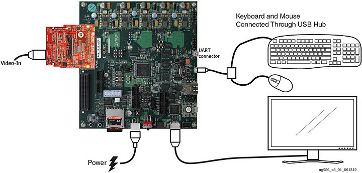
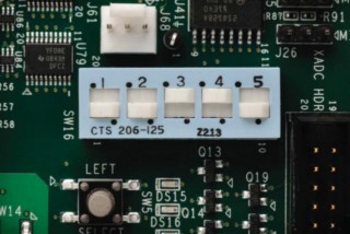
- Set the boot mode switch SW16 to SD boot mode.
- Connect a Laptop or PC to the Mini USB port J17 on the ZC702 board for UART communication (Optional for Linux Qt application). Use the following serial port settings:
Baud Rate: 115200
Data: 8 bit
Parity: None
Stop: 1 bit
Flow Control: None
7.2 Running the Standalone Software Application
The standalone SD-card image requires the following components:
| BOOT.bin | Standalone boot image (6.7) |
| sepia.bin | Partial Sepia bitstreams (4.9) |
| sobel.bin | Partial Sobel bitstreams (4.9) |
Shortcut: A pre-built standalone SD-card image is available at zc702_pr_rd/sd/standalone.
Tutorial
- Copy the standalone SD-card image to the top-level directory of a FAT-32 formatted SD card.
- Insert the card into the SD card slot on the ZC702 board.
- Power on the ZC702 board.
- Connect your terminal emulator software (e.g. TeraTerm) to the serial port assigned to the Silicon Labs CP210x USB to UART Bridge.
- The standalone application will start automatically.
- To operate the standalone application, enter the desired number in the terminal window and observe the monitor output.

7.3 Running the Linux Software Application(s)
The Linux SD-card image requires the following components:
| BOOT.bin | Linux boot image ( 6.8) |
| devicetree.dtb | Device tree blob (5.2) |
| devicetree.dts | Device tree source (5.2) |
| filter_cmd | Linux command line application (6.4) |
| filter_qt | Linux Qt application (6.5) |
| images/ | Directory with pictures used by Linux Qt application (6.5) |
| init.sh | Setup script (5.3) |
| qt_lib.img | Qt/Qwt libraries image file (6.5) |
| run_filter.sh | Wrapper script (7.3) |
| sepia.bin | Partial Sepia bitstreams (4.9) |
| sobel.bin | Partial Sobel bitstreams (4.9) |
| uImage | Linux kernel image (5.2) |
| uramdisk.image.gz | Linux root file system (5.3) |
Shortcut: A pre-built Linux SD-card image is available at zc702_pr_rd/sd/linux.
Tutorial
- Copy the Linux SD-card image to the top-level directory of a FAT-32 formatted SD card.
- Insert the card into the SD card slot on the ZC702 board.
- Power on the ZC702 board.
- Connect your terminal emulator software (e.g. TeraTerm) to the serial port assigned to the Silicon Labs CP210x USB to UART Bridge.
- The Qt application will start automatically after Linux is booted.
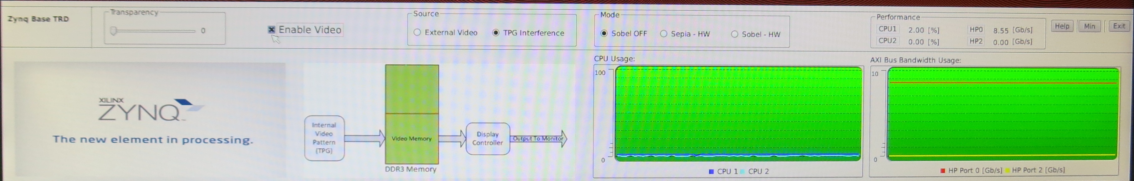
- Use the mouse to navigate the Qt GUI. The GUI has the following features (from left to right):
Transparency slider
Enable Video button
Source Select radio buttons
Filter Mode radio buttons
Textual Performance Monitor: CPU usage and AXI HP0/2 memory throughput
Help, Min, Exit control buttons
Zynq logo
Data flow graph based on Source and Mode selection
Graphical CPU usage monitor
Graphical AXI HP0/2 memory throughput monitor - Click the Min button to hide the Zynq logo, Data flow graph, and the graphical CPU / AXI HP monitors. Click the Help button to display additional information. Click the Exit button to exit the Qt application.
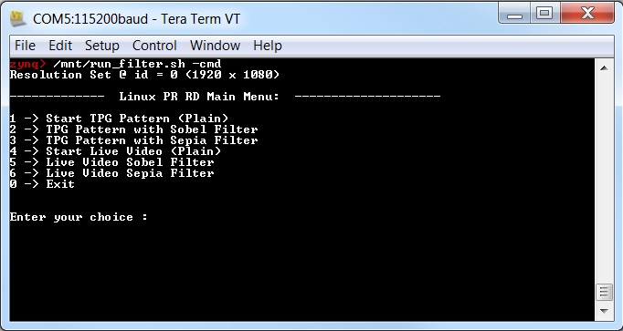
- To restart the Qt application, change directory to /mnt, then type ./run_filter.sh -qt at the zynq prompt in either the terminal window or on the monitor display. Alternatively, to start the command line application, type ./run_filter.sh -cmd at the zynq prompt in the terminal window. The file run_filter.sh is a wrapper script that runs the corresponding Qt or command line executable and sets the required Qt environment variables.
- To operate the command line application, enter the desired number in the terminal window, press enter, and observe the monitor output.
- The default video resolution is set to 1080p. To change the video resolution to 720p, use a text editor (e.g. vi) to open the file /mnt/devicetree.dts. Search for the line starting with videomode and set the resolution to "1280x720".
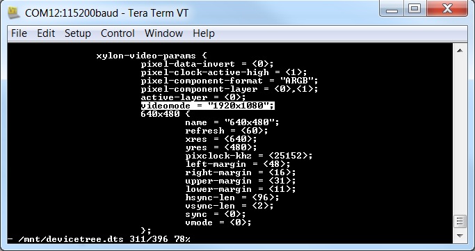
- Save the file.
- Re-compile the devicetree by typing dtc -I dts -O dtb -o /mnt/devicetree.dtb /mnt/devicetree.dts at the zynq prompt.
- Type halt at the zynq prompt to shutdown Linux.
- Power-cycle the ZC702 board or press the POR (power-on-reset) button. The new video resolution will be active after re-boot.
References:
- XAPP1159,Partial Reconfiguration of a Hardware Accelerator on Zynq-7000 SoC Devices
- UG925Zynq-7000 EPP ZC702 Base Targeted Reference Design
- XAPP890,Zynq SoC Sobel Filter Implementation Using the Vivado HLS Tool
- UG821,Zynq-7000 EPP Software Developers Guide
- UG926,Zynq-7000 EPP ZC702 Evaluation Kit
Additional Documentation:
© Copyright 2019 - 2022 Xilinx Inc. Privacy Policy