Utilizing PS memory to execute Microblaze application on Zynq Ultrascale
In this demo we will see how to utilize the Zynq UltraScale+ PS memories, DDR and OCM, to execute the MicroBlaze code. We will also use the PS UART to display the STDIN/OUT info from our application. There are a few caveats to this flow that are covered in the steps below.
Table of Contents
Configuring the Zynq UltraScale PS/PL interfaces:
Here, I have enabled the Slave port to allow access to the OCM/DDR (HP), and the PS UART (LPD):
Also, enable the fragmentation so we can use the PS_UART:
In this demo, we shall be using no LMB/AXI BRAM for the Microblaze. So, we will need to hold the Microblaze in reset, while the PSU
is configured. We can then wakeup by toggling a GPIO pin. I also enabled the GPIO via the EMIO here to do this: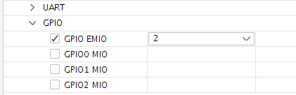
Setting the Address Map:
I am using the UART on the PS, and the OCM/DDR. So, make sure these are mapped: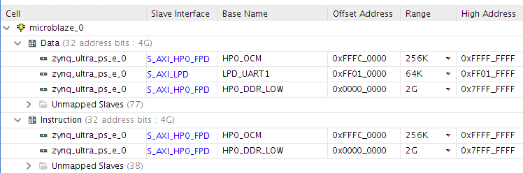
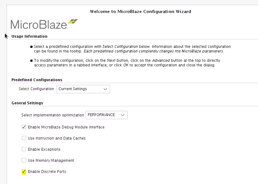
Configuring the Microblaze:
I added the Microblaze and enabled the AXI Instruction and data interface:
Note: Here, I am not using any BRAM in the PL for the MB, and will use the OCM instead. Users can use BRAM here, and place some section in BRAM and others in the OCM as they deem fit.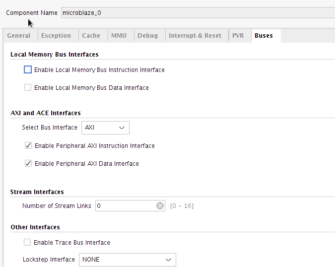
I set the Vector Base Address to the PS OCM: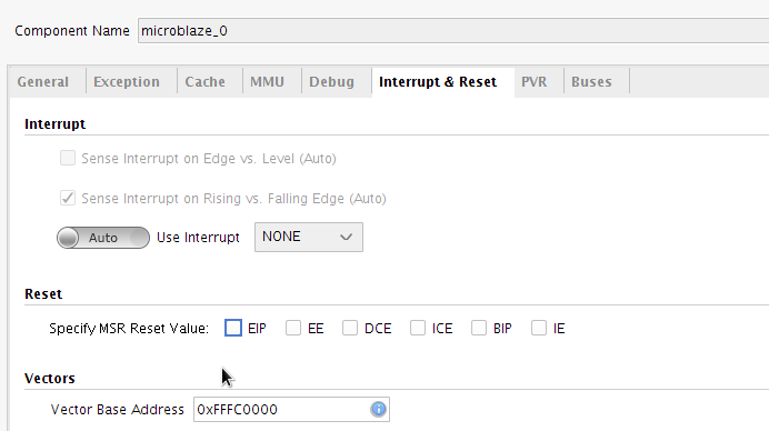
Note: if the DDR was used here, this would be the base address of the DDR (0x00000000 in this case)
Note: the Microblaze will attempt to load from the vector base address upon coming out of reset. If using a bootloader (FSBL), then the
Microblaze could come out of reset before the application code is available. To prevent this, we can hold the Microblaze in reset.
Enable the discrete ports on the Microblaze:
Then connect the GPIO Output to the wakeup, and use the constant IP to set the reset_mode to 01: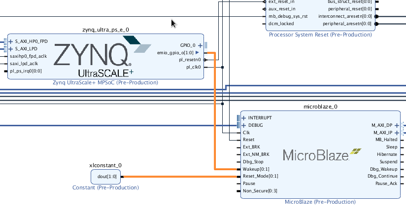
Generate Output products, create HDL wrapper, and generate bitstream and export to SDK (include bitstream)
Create SDK application Project:
In SDK, create a Hello world application template for the Microblaze:
Next, choose hello world, and Finish.
Right click on the newly created application in the project explorer, and select Generate Linker Script: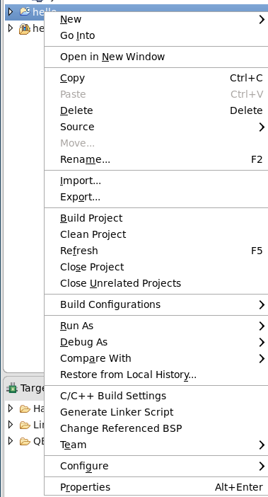
Place all sections in OCM/DDR: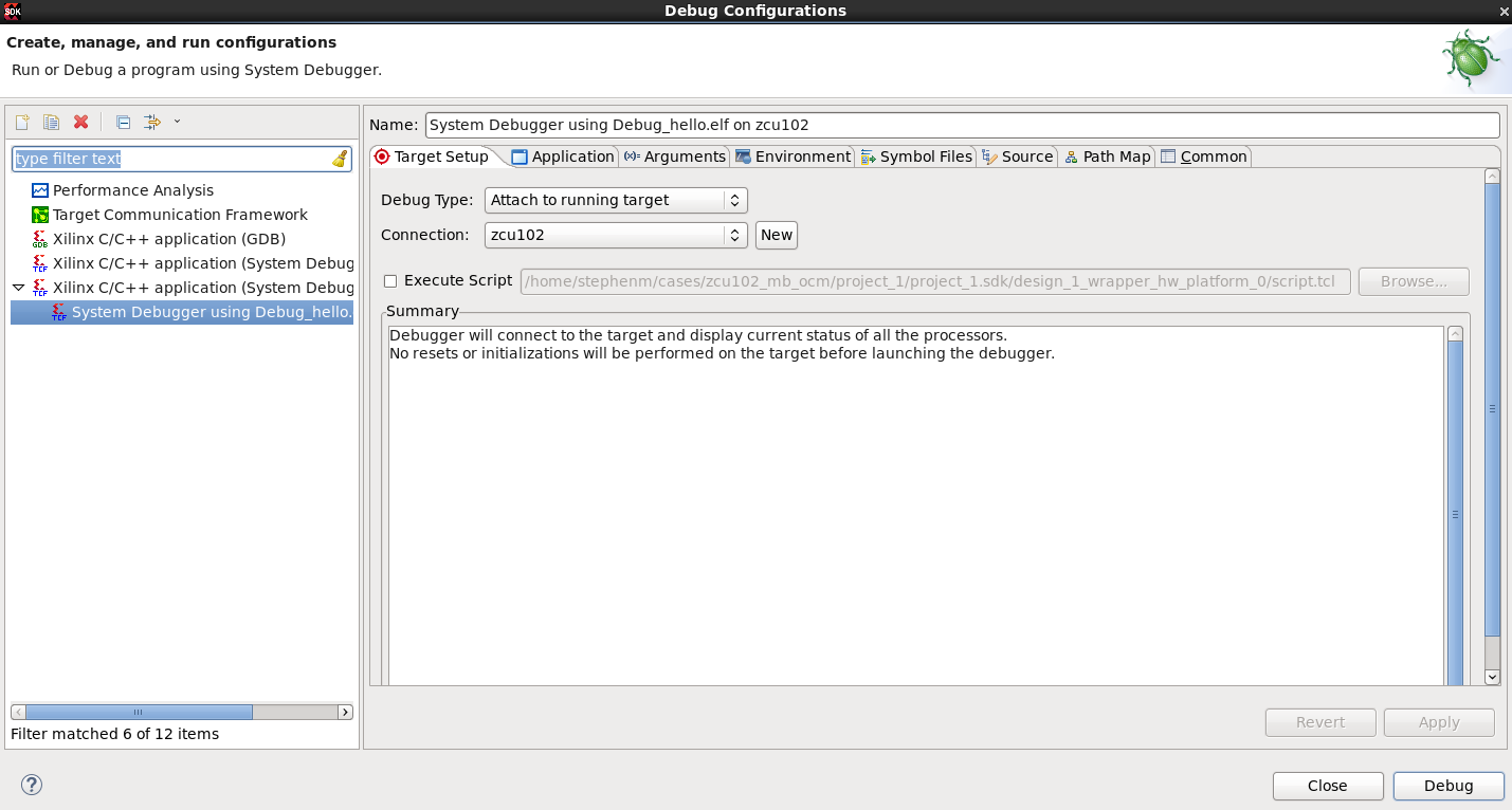
Set the STDIN/OUT. To do this, right click on the BSP in project explorer and select Board Support Package Settings:
Note:
There is a caveat here, in that we can’t use the FSBL to configure the PSU, as we are using this to store the hello world application in OCM.
So, we will need to do this via a TCL script:
connect
source psu_init.tcl
targets -set -filter {name =~ "PSU"}
puts "Configuring PSU"
psu_init
psu_ps_pl_reset_config
psu_post_config
psu_ps_pl_isolation_removal
fpga -no-rev -f design_1_wrapper.bit

mwr 0xffff0000 0x14000000
mwr 0xFD1A0104 0x380E
targets -set -filter {name =~ "Cortex-A53 #0"}
dow ../hello/Debug/hello.elf

#Toggle GPIO 0
mwr 0xff0a02c4 0x1
mwr 0xff0a004c 0x1
The script above will configure the PSU, then download the ELF. The A53 is used to download the ELF, so this needs to be brought out of reset. Finally, the GPIO is toggled to wake-up the Microblaze.
This script can be sourced in the XSCT (Xilinx XSCT console)
If users are using the DDR, then they can toggle the GPIO from the FSBL code by adding the lines below into the xfsbl_hooks.c in the XFsbl_HookBeforeFallback function:
Xil_Out32(0xff0a02c4, 0x1);
Xil_Out32(0xff0a004c, 0x1);
Note: you will need to add the xil_io.h include at the top of the xfsbl_hooks.c
Then to create the boot image, using the Boot Image creation tool in SDK, and boot the device.
Debugging the application:
Note: It is assumed that the user has configured the PSU either via the script provided above (if using OCM), or the modified FSBL (if using DDR) using the steps detailed above
before continuing here.
The SDK debugger supports debugging on a running target so lets set this up. To do this, right click on the application in the project explorer and select Debug as -> Debug Configurations.
Then double click on the Xilinx C/C++ application (System Debugger):
Set the Debug Type to Attach to running target and select Debug
Once the debug Perspective opens, drop to the Microblaze: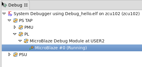
Then in the XSCT, do a rst on the Microblaze: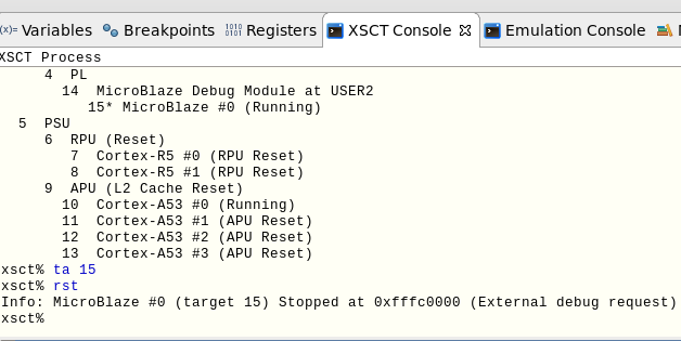
You will need to target the Microblaze first using the targets command (or ta for short)
Make sure that there is a breakpoint set in the main:
Then do a resume (F8), and this will just to the breakpoint you have set. User can now user the SDK debugger as usual.
Note: Make sure that the symbol information is set. To do this, right click on the processor (Microblaze #0), and select add symbol file and point to your ELF, and set the address 0xfffc0000.
Also, just open the application c file too if it doesn’t manually open.
Related Links
© Copyright 2019 - 2022 Xilinx Inc. Privacy Policy