Understanding MEMDATA flow and how to manually create MMI file
Table of Contents
Introduction:
In order to populate the BRAMs with a data file (ELF or MEM file), the Vivado tools need to know the overall BRAM block size and the BRAM location, width, and type that this BRAM block is composed of. The tools need to know how this BRAM Block is connected to the Processor. All this information is provided to the tools by metadata passed in BMM_INFO_* properties either in the HDL attributes, or cell properties in the implemented design.
So in this article, we shall discuss how this flow works, and how to manually create the files needed if this flow breaks, or if a user design falls outside the supported flows within IP Integrator.
Memdata Metadata:
In order to investigate the memdata metadata, I have created the Block Design (BD) with a Microblaze with 64kb LMB BRAM memory: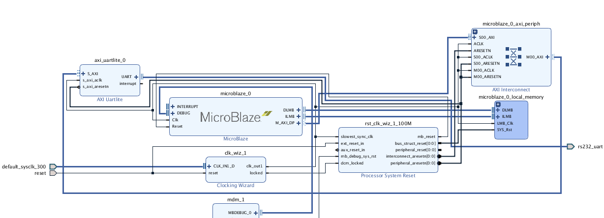
The address map for this BD can be shown below:

Note: The Vivado uses the address in the Vector Base Address in the Microblaze configuration as the boot address for the Microblaze.
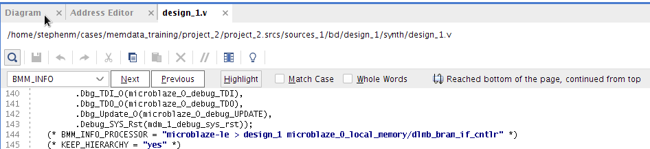
Once the Output Products are run on the BD, then the HDL attribute properties will be populated automatically by the tools. For example, we can view this in the HDL for the BD:
This can also be read from the block properties for the Microblaze IP too:
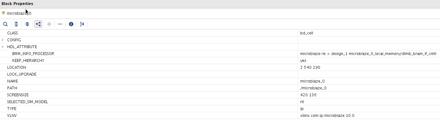
Here we can see all the memory controllers in the address space of the Microblaze. If we had an AXI BRAM controller added, then this would be present here too.
We can follow this “chain” to all the memory controllers in the address space. In this case the dlmb_bram_if_cntlr:

Again, we can read the block properties for the dlmb_bram_if_cntlr:
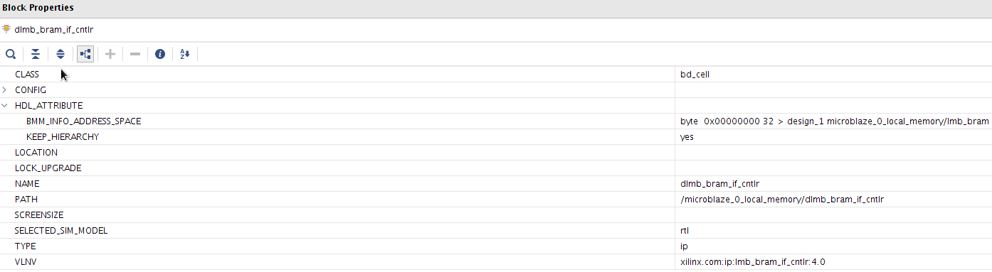
Here we can see all the BRAM modules connected to the memory controllers. In this case it is the lmb_bram. The lmb_bram block is created using the Block Memory Generator (BMG).
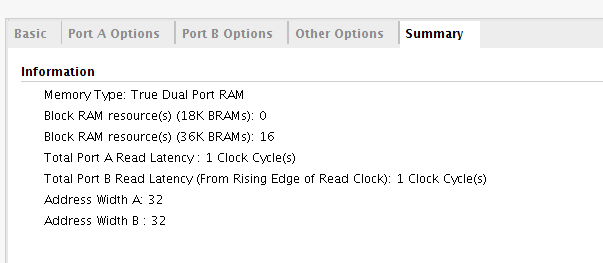
As mentioned above, the address range was 64KB, or 65536 Bytes. Vivado synth will target a RAMB36. The RAMB36 primitive is a 32 bits data + 4 bits parity. The tools won’t use the parity*, so we will use 32 bits for our calculation.
So, 32 x 1024 = 32768 bits, or 4096 Bytes per BRAM. So, since we need 65536 Bytes, then we will need 65536 / 4096 = 16 RAMB36 BRAMs for out lmb_bram.
*Note: XPM modules will utilize the parity bits. However, it is not used here.
If we open the summary for the LMB_BRAM (BMG), this is as expected:
We should also see this if we open the implemented design, and search (Ctrl + f) for the BRAM cells:

Here, we can see that there are indeed 16 instances of the BRAMs that make up our lmb_bram block memory:

Each of these cells have a bmm_info_memory_device property that the tools use to know how to parse the ELF across the BRAM.
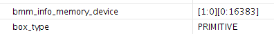
Also, the location information for the BRAM cell can be found here too:

So, to summarize. The Vivado tools will use the BMM_INFO_* metadata to determine the processor -> bram controller -> bram -> bram instances to populate the BRAM with the ELF file.
The ELF has file properties called SCOPED_TO_CELLS (STC), and SCOPED_TO_REF (STR) to associate the ELF with a processor. Where the STC is the processor cell name, and the STR is the module where the STC resides.
There is a GUI in Vivado Tools to do this:
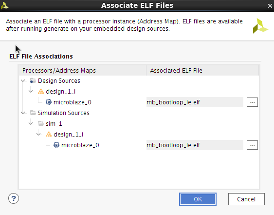
This can also be set from the TCL console. I have shown the Netlist view to demonstrate how to determine the STC (microblaze_0), and the STR which is the module name
where the STC resides (design_1):

set_property SCOPED_TO_CELLS microblaze_0 [get_files *.elf]
set_property SCOPED_TO_REF design_1 [get_files *.elf]
This metadata is also used to create the MMI file that is used by the Updatemem tool in SDK. This can also be created using the TCL command here:
write_mem_info <mmi file name>.mmi
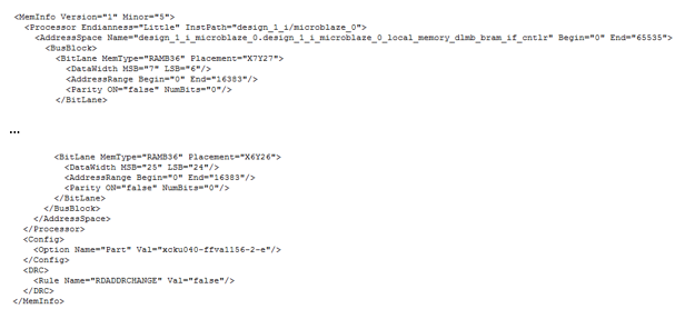
As we can see here, the information from the BMM_INFO_* properties is used to populate this file too. For example the BMM_INFO_PROCESSOR property is used to populate the <processor> cell info. The BMM_INFO_ADDRESS_SPACE property is used to populate the <AddressSpace> cell, or cells if more than one BRAM controller. Finally, the bmm_info_memory_device properties is used to populate the <BusBlock> cells.
Users will also note, that the data is swapped (byte and nibble). For example for a 32 bit wide, 16 BRAMs would look like:
- 7:6, 5:4, 3:2, 1:0, 15:14,13:12,11:10,9:8,23:22,21:20,19:18,17:16,31:30,29:28,27:26,25:24
Similarly for 8 BRAMs (ie each block is 4 bits wide):
- 7:4, 3:0,15:12,11:8,23:20,19:16,31:28,27:24
However, this is just for the Microblaze. If users are using a non-processor flow with an external third party processor then the parsing here would depend on how the processor expects the data to be presented.
To summarize, the Updatemem tool can populate the BRAM with an ELF/MEM file. However, this file uses the information in the MMI file. However, the MMI file users the BMM_INFO_* properties in Vivado and since we have already discovered if the BMM_INFO_* property “chain” is broken, then this file will not be created either. So, in this case the MMI file will need to be created manually. This will be discussed in the next step.
Manually creating the MMI file:
In the previous section, we have discussed how the Vivado tool will autogenerate the MMI file. We have learned how this is created using the BMM_INFO_* properties. So, we can use the same approach to manually create this MMI file.Taking the hardware design used above and assuming we don’t have access to the BMM_INFO_* properties, we can still populate the MMI. What we need is:
- Device Part
- Address Range
- Amount of BRAMs
- BRAM Type
- BRAM Width
- BRAM Location
Address Range:
This can be obtained from the address editor:In the MMI file this will look like:
Note: this is in decimal.
Begin="0" End="65535"
Amount of BRAMs:
The address range specified here is 64KB, or 65536 Bytes. The tools will target a RAMB36 here. The RAMB36 primitive is a 32 bits data + 4 bits parity. The tools won’t use the parity, so we will use 32 bits for our calculation.32 x 1024 = 32768 bits, or 4096 Bytes per BRAM. Since we need 65536 Bytes, then we will need 65536 / 4096 = 16 RAMB36 BRAMs
BRAM Type:
This can be obtained by opening the implemented design, and search for the BRAM primitives:Then highlight each cell, and view the cell properties. The BRAM type will be listed here:

This would be used to populate the MemType for each BRAM in the MMI:
<BitLane MemType="RAMB36" Placement="X0Y0">
BRAM Width:
Again in the cell property, the user can see the Width:
This would be used to populate the DataWidth information for each BRAM in the MMI:
<DataWidth MSB="7" LSB="6"/>
BRAM location:
Again in the cell property, the user can see the LOC:This information would be used to populate the Placement information per BRAM in the MMI:
<BitLane MemType="RAMBXX" Placement="X7Y26">
MemInfo:
The MemInfo version for 2018.1 should be<MemInfo Version="1" Minor="5">
Processor Info:
The Processor Endianess for Microblaze should be Little:<Processor Endianness="Little" InstPath="XXXX">
InstPath:
The InstPath string does not matter, once it matches the string given in by the -proc switch in the updatemem utility:<Processor Endianness="XXXX" InstPath="my_bram">
AddressSpace Name:
The Address Space name doesn’t matter:
<AddressSpace Name="my_local_bram" Begin="X" End="XXXXX">
Using the updatemem utility to populate the BRAM:
The updatemem command line can be called for XSCT, or from Vivado. User should use the updatemem -help for guidance on using this utility. This is also covered in chapter 7 in the Vivado Embedded Design guide doc here.However, below is a template:
updatemem -meminfo test.mmi -data test.elf -bit design_1_wrapper.bit -proc my_bram -out download.bit
Conclusion:
Users should have a better understanding of how the Vivado tools use the metadata to populate the BRAM, or create the MMI file. Users should understand how this could potentially break. Finally, users should be in a better positions to manually create an MMI file to be utilized in the Updatemem utility.Related Links
© Copyright 2019 - 2022 Xilinx Inc. Privacy Policy